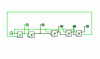
hmm, I can see from your description of the Johnson counter that it counts in gray code. Two bits would be: 00,10,11,01,00... (4 states,thus divide by 4) and this is done when feeding the output back to the input. If we add another counter to that we get a third output and the sequence would be: 000,100,110,111,011,001,000 which gives us 7 states! (i.e divide by 7) now in my divide by 10 case I need at least 10 states so using 5 bistable's I would get:
00000
10000
11000
11100
11110
11111
01111
00111
00011
00001
10 States, thus divide by 10 without any gates?!!! (is that how it works basically)?