Electro Tech is an online community (with over 170,000 members) who enjoy talking about and building electronic circuits, projects and gadgets. To participate you need to register. Registration is free. Click here to register now.
Welcome to our site! Electro Tech is an online community (with over 170,000 members) who enjoy talking about and building electronic circuits, projects and gadgets. To participate you need to register. Registration is free. Click here to register now.
I want to build an alternator voltage regulator so I'm looking for a simple PWM controller so I don't have to build an oscillator and add a comparator to it. It needs to be able to go from 0 to 100% duty cycle. Anyone know of such a beast?
Single or 3 phase alternator Ron? Like for an example an automotive alternator? Automotive has become relative easy with a good number of single chip solutions like the broken link removed L9407F. If you want PWM there will be an oscillator be it build it or buy a packaged affair. I guess it really depends on what exactly you want to regulate or control?
Yes, sorry I should have elaborated. It's a big old 250 amp automotive one (custom) for either a 12 volt battery or two 8 volt ones in series. that would like 12 or 13 amps of field current. He wants to be able to set the charge voltage. The field is grounded. It's for someone else to build so I'm trying to keep it simple as far a parts count goes. Right now I just have a triangle wave and a comparator with a big PFET.
Sorry, Yes it is a big custom automotive type that would like about 13 amps of field current. It is for a 12 volt system or two 8 volts in series so it needs to be adjustable. It's for someone else to build so I trying to keep the build simple. Right no I have a triangle wave an adjustable error amp and a comparator and driver feeding a big PFET. That may be as simple as it gets. I thought I might find a chip with an oscillator, and comparator in one IC, but I haven't been able to find one yet.
I may be wrong, but doesn't the rotating field in an automotive alternator only control the current output? Always thought/heard that voltage was a result of the number of turns in the stator winding. And the current limit was a result of the wire gauge used in those turns.
Sorry, Yes it is a big custom automotive type that would like about 13 amps of field current. It is for a 12 volt system or two 8 volts in series so it needs to be adjustable. It's for someone else to build so I trying to keep the build simple. Right no I have a triangle wave an adjustable error amp and a comparator and driver feeding a big PFET. That may be as simple as it gets. I thought I might find a chip with an oscillator, and comparator in one IC, but I haven't been able to find one yet.
Ron, I am purely guessing on this but that is a big unit, although I have seen 300 amp units on some major emergency vehicles. Actually surprised that they deliver that much with the field current you mention. The guy who had a good handle on this sort of stuff was tcmtech, he was always into stuff like that but have no clue if he still frequents this place. I don't know of anything off the shelf like the chip I suggested that will give yu exactly what you want, however, I would approach it exactly as you are using a triangle waveform oscillator and a comparator type design. Then let it drive a big high current MOSFET to push the field windings. The 16 volts shouldn't be a problem either. I just don't know of an off the shelf turn key solution. Hell, it sounds like you are on the right track with your approach. I simply don't have a solution off the cuff and would be doing exactly what you are doing.
I may be wrong, but doesn't the rotating field in an automotive alternator only control the current output? Always thought/heard that voltage was a result of the number of turns in the stator winding. And the current limit was a result of the wire gauge used in those turns.
No, yes and maybe. The versions I am familiar with going back to the 60s the answer would be no. If you drive the field with a higher voltage and current the alternator will increase the voltage out. However, I have recently read that in some cases and I haven't a clue which models or versions actually have the ECU (Computer) controlling the alternator based on a collection of data including things like data from temperature sensors. Speaking for the GMC trucks I have? The answer would be No. You drive the field and the voltage and current out will increase. Matter of fact if we disconnect the stator diode bridge you get a pretty good 3 phase AC generator going. The problem is that we now have so many types of alternators out there. Wow and my first cars actually had a generator with a mechanical contact system for the regulator. Alternators were a great invention that came later in my life.
So while I am not familiar with a version like you mention simply means I haven't seen one but as I said I have read where there are versions using the ECU to regulate alternator output. It wouldn't surprise me, that's for sure.
Yeah, I'm from the generator and mechanical regulator/cutout era, too. Was under the understanding though that in an alternator, even though they still call it "voltage regulation", the reality is it is current regulation. While a generator is voltage and current regulation. Learn something new everyday.
Still remember the "box" you could buy in Popular Mechanics and the other magazines to convert your alternator to run power tools with.
Hi. Yes, it's like the ones on police cars and ambulances. I'm not sure how you optimize them - I think that's the trick, but I think it is like Ron says voltage and current. The battery will demand more current as the voltage rises. And if it is turning to slow not enough voltage to get above the battery. I think that is the emergency vehicle problem. They are at idle with a lot of stuff on and the alternator can't keep up at the low rpm.
Actually the way I'm looking at is not as bad as I thought it might be.
The Circuits Monitors the Alternators Output Voltage and compares it to a Zener Reference.
This in turn drives a Transistor to control the current to the Alternators field coil.
Typically Regulated to about 14.5 Volts and this is a Pretty Stable Voltage.
When a car battery is Low, it will charge at a High current.
The Closer the battery gets to this 14.5 volts, the Lower the current draw will be.
At Full charge, it will only be a few milliamps of charge current.
If wanted, An Additional Resistor can also be added to Limit Maximum Charge current on a low charged battery.
Thanks Alec. I was looking for ease of assembly, so was thinking of an IC with only an R & C plus the input to a comparator. But no joy. I'm beginning to wonder if I am making it to hard, because it looks like Chemelec's regulators just turn on the field if the battery voltage is below say 14.5 volts. It just seemed to me that with a 250 amp regulator something gentler might be in order. I was thinking just keeping the voltage above 13v under load.
Thanks Alec. I was looking for ease of assembly, so was thinking of an IC with only an R & C plus the input to a comparator. But no joy. I'm beginning to wonder if I am making it to hard, because it looks like Chemelec's regulators just turn on the field if the battery voltage is below say 14.5 volts. It just seemed to me that with a 250 amp regulator something gentler might be in order. I was thinking just keeping the voltage above 13v under load.
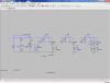
OK. So after talking with Chemelec I came up with this one based on an adjustable voltage reference.
The reference supplies the adjustability as well as acting like a comparator to sharpen up the turn on/off voltage. The cap on the regulator insures stability as well as making the maximum switching frequency some reasonable frequency. The 7002 inverts it and allows for the multiple alternators to be turned on and off.
The gate resistors make turn on/off kind of slow which hopefully will reduce EMI.
I'm looking for inputs in case I have it all wrong..
I've run a sim of that circuit but I'm not seeing any regulation or PWM effect. U3 does not have a zener-like effect. The voltage across U3 simply follows (albeit with reduced amplitude because of the R1/R5 potential divider) the V1 supply voltage, so M1 stays conducting unless that voltage is very low (the M1 turn on threshold), and it does not switch cleanly.
Can you clarify the intended circuit operation?
In general there are three pases that are combined in the stationary part of the alternator, so you get 3 phase rectified output.
The rotor is the magnetic field that's changed. Usually the slip rings runs on two brushes, I've seen one at 90 and both at 90 degrees. Generally, that rotor is isolated. Not sure you have to get the polarity right. I doubt it, because of the rectification.
One end of the rotor is tied to +12 and the other is chopped to ground, so I think it can be a simple comparator, but you have options of: On/OFF, PWM, or current controlled.
Not exactly sure what drives the idiot light. I do know that if the wires to the rotor are severed (I had a weld break), the idiot light stays off even though the alternator is not working.
Some alternators (GM) had a test point, but getting to it was tough. You grounded a tap sticking out of the internal regulator and it forced the rotor full on or max charging current.
My quick and dirty tests are to measure the voltage drop when the alternator is good from the + of the battery to the + of the alternator with lots of accessories on: lights heater and AC and record it.
Then I usually throw a scope on it to diagnose problems. Most of the time you could replace the regulator and or diodes, but now - who knows. You find spot welded diodes, a bad bearing or bad insulation or that broken wire on the rotor.
This site uses cookies to help personalise content, tailor your experience and to keep you logged in if you register.
By continuing to use this site, you are consenting to our use of cookies.

")