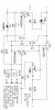
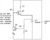
Okies I have a bunch (2000+) of never used but dropped down to 0V LiFePO4's now I dun expect all of them to revive, matter of fact I already got my money's worth with the ones that were at a higher than 0V and most of those seem to be holding a charge fine. Anyways I attached a picture of my circuit. this is what I'm thinking the Q1 MPSA06 is happily letting through 107mA which the 47 ohm resistor will let through. when the battery being charged rises in voltage to 3.31V the input into the base of Q2 rises to .7V at that time the base of Q1 get's starved until the voltage in the li-FePO4 cell drops below 3.3V then q2 turns back off and the charging will continue again untill the cell rises past 3.31V again so the LED will flash when the cell is precharged to 3.3V and the LED will keep flashing and the cell won't be able to charge past this point, which means it's protected as well.
The when I see them flashing I can put them in my real charging circuit CC/CV to 3.65V it's just the cells being stored that long shouldn't be exposed to .5A of current till there in the normal voltage range for the cell. .1C is enough for the precharging.
Will this circuit work am I missing something did I get something wrong?
BTW I'm kinda married to the NPN's cause they were 4.5c each and these circuits (I'm gonna make 20 of em, they are only gonna be used for a few times till I have charged all the cells once then shelved, so cheap and dirty is the goal here.
terramir
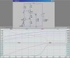

 . I thought I was using the transistors as switches, I saw his graph and it seems like the current stops rising but still continues flowing once the led goes on
  this is not what I wanted to accomplish