Continue to Site

Welcome to our site!

Electro Tech is an online community (with over 170,000 members) who enjoy talking about and building electronic circuits, projects and gadgets. To participate you need to register. Registration is free. Click here to register now.

  • Welcome to our site! Electro Tech is an online community (with over 170,000 members) who enjoy talking about and building electronic circuits, projects and gadgets. To participate you need to register. Registration is free. Click here to register now.

simple precharging circuit will this work?

Status
Not open for further replies.
Yes, V SET = 1.8 has been measured from ground. Just to confuse: if you measure from 5V, it will be 3.2V.
:D :LOL: yeah just to confuse LOL
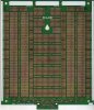
Well tommorow I will have that circuit breadboarded I assume and up and running I still gotta finish 3 chargers, well solder in the lm317's shave some fiberglass off the side of the board to make it fit in my case (a older samsung handsfree setup Case) Anyone know why that thing would have three discrete switching voltage regulators inside :S 2x L 4971's and one lm2575T in addition to that there is
a quad opamp on this board to bad it's an smd KA3403D a TDA1905 Audio amplifier and well a bunch of coils etc. considering I paid a buck per I'm making out like a bandit the rubicon caps alone are worth way more :p
But the project boxes hey they are cheap enough for that alone :p
Also another question Anyone know why I'm pulling a blank on looking up 1RF (or HF) 9540 there some sort of mosfet (S D G labeled on the board) There marked with the F symbol for fairchild but on the fairchild website I can't find jack about them. Hey I got ten of these boards one of these days I'll think u8p some projects where at least some of the parts will come in handy.
terramir
 
If you add a couple of resistors, you can get a lot more resolution from your pot. The attached modification gives you a nominal peak battery voltage range of about 3.1V to 3.7V. The hysteresis is about 180mV.
These numbers are from an LTspice simulation.
I say nominal because resistor tolerances will change the range somewhat.
 

Attachments

  • Liprecharge1.PNG
    Liprecharge1.PNG
    18 KB · Views: 118
If you add a couple of resistors, you can get a lot more resolution from your pot. The attached modification gives you a nominal peak battery voltage range of about 3.1V to 3.7V. The hysteresis is about 180mV.
These numbers are from an LTspice simulation.
I say nominal because resistor tolerances will change the range somewhat.

ehhh I got plenty of 1k one turn pots however for this circuit I bought 2 500 Ohm multiturn pots figuring that would be better by any chance can you tell me how to do this with the 500Ohm one on both sides Iset as well because I want to be exact when it comes to the charging current as well. I'll be pre-charging and charging groups of 5 random cells in 12 groups
4 groups charged with 100 mA to 3.3 and 3.4 respectivly
4groups charged with 50 mA to 3.3 and 3.4
4 groups charged with 200mA to 3.3 and 3.4 respectivly
then all groups will be charged with the other charger to full
then 2 out of the 4 in each catagory will be discharged with a load for about 1 hour at 200mA rate and then recharged after this they will be left to sit for two days then I'll look for trends in the retention rate.
ty for all your help
terramir
 
Last edited:
ehh got a question about tolerances in this circuit to be specific
My thinking is thwe following R1,3,4,5 will not have much opf an impact on the specs of the circuit, however variation in R2 will effect the current (btw they all measure in the 4.3 ohm range so either my meter is off or they are out of spec (all gold 4th ring should be with-in 5%) am I correct in assuming that that is they only one that will mess with the circuits specs drastically ?
terramir
 
4 groups charged with 200mA to 3.3 and 3.4 respectivly
This current would cause Q1 to dissipate up to ~900mW. The MPSA06 is rated to 625mW. You may have to double up your transistor or use a different type.
 
This current would cause Q1 to dissipate up to ~900mW. The MPSA06 is rated to 625mW. You may have to double up your transistor or use a different type.

can I just parallel two transistors like that I mean just stick an additional transistor in the breadboard in those three lines (i.e. e e, b b, c c,) cause there's room for that :) and I got like 60 left to use :p
terramir
 
It's not ideal - they won't share the load equally - but it might work. Give it a go and see for yourself.
 
Parallel BJTs are prone to thermal runaway when they start to heat up - The one with the lowest Vbe draws the most current. Vbe has a negative temperature coefficient, so the Vbe drops even more, and...:eek:.
Your best bet might be to use an emitter resistor per transistor, and set the control voltage for 100mA. For slightly improved accuracy, use summing resistors (see attached).
 

Attachments

  • Liprecharge2.PNG
    Liprecharge2.PNG
    19.3 KB · Views: 134
okies I got a problem of a different kind I put ten of these circuits on ran into two problems #1
adjusting the pots I used a calculator and got the values I should have on 500 ohm trimmers adjusted the voltage one to 332 and 174 ohms and it works I get very close to 1.7V mind you as soon as I stick the other pot in there I cannot properly adjust that one I figured about 453 and 47 ohms should give me about .47 V nice and good except when I run the circuit it ends up being 4.9V between the ground and pin3 and the battery gets fed with 260 mA either I f'ed up the circuit or something else is going on. I mean I did the math correctly and everything is common except for the individual cells negative pole so that seems like that is what's supposed to happen except for the massive current flow. the LED's light if there is no cell it goes off if you put a cell in the slot and it should go back on when it's done.
Edit by me NVM figured it out the jumper to the gound was off by one works like a charm now although my 4.7ohm resistors are more like 4.3 so I had to fine adjust it while the circuit was running all cells are charging at 100mA +/- 2mA now. so it's all good as long as the cut-off voltage is right.

PS: I might test at 150 instead of 200 for the high group since messing with the circuiot now would be a real pain in the arse I may have over 3000 insertion points but the wire jumpers and all that is so crowded that it would be a real pain.
check out the top of my breadboard/designer kit, now if I could get someone to make me single sided cheap boards with silkscreen outlining what is connected I would have a great way to make my projects :p
 

Attachments

  • Scan10024.JPG
    Scan10024.JPG
    177.9 KB · Views: 127
Last edited:
It's best to set the pots with the circuit powered up. The battery should NOT be in-circuit.

1) You can put an ammeter from Q1 collector to 5V to set I SET.

2) To check the voltage trip points, connect a variable voltage (maybe 0-3V) from 0V to Q1 collector. Put a voltmeter between Q1 collector and 5V and sweep the voltage up & down to find the set points by looking at the LED (& meter). Adjust V SET pot accordingly.

NB Ensure you use a voltmeter where mentioned, using an ammeter when the variable voltage is connected will wreck something!
 
Last edited:
well it's arounf 1.7volts like 1.689V on the Vset so I'm charging a round right now I will be chaecking the cell voltages periodically and if it goes a bit to high for my taste I'll adjust it before the next round I won't leave this thing unsupervised until it's properly adjusted.

What you think of my hightech breadboard LOL if I could get singlesided boards for it in copper I might just start to solder projects even these kind, to bad the company went belly up years ago. Cause if I could get some boards like this cheaply I would just have to close it flip it around and solder the stuff

terramir
BTW would this circuit work with a KA3403D, Cause if I could get them desoldered of the samsung boards I could make another 20 precharging circuits :p Although I would have to etch a board for it cause it's an SMD

terramir
 
Last edited:
okies I think there is trouble in paradise. the led's go on before the charging is complete. or the charging continues even though the lights are lit up.
the lights go on slightly before 3V however the cells continue charging right now the cells are between 2.98 and 3.2V however the led's are lit on all circuits.
I thought the lights would't go on till the current is interupted to the cells.
Help
terramir
 
The LED should be either fully on or fully off. If it's not, assuming you've wired it correctly, then it would mean that the cell is not holding its charge properly - so it reaches 3.3, charge current stops, cell voltage quickly reduces to 3.1 (or whatever) which starts it up again. If you have a CRO, you can check if there's an oscillation on the LED, or if no CRO, connect a speaker/earphone across the LED and you should be able to hear the oscillation...depending on how good your hearing is.

Actually, if you connect a capacitor across the 1.8M resistor, maybe 1-10uf, if oscillation is the problem, then the LED will visibly flash. (i think)
 
Last edited:
according to my dmm the frequency across the led is 0 hz also when I take the cells out they don't dramtically drop in voltage it takes some time 10sec plus for it to drop less than .1 volts and it usually stablizes after that. So something else is wrong. :( 
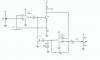
I dunno how op-amps really work but it doesn't seem to have a clean turn on for led and Q2 point.
I plugged it in exactly like in the schematic that I revised based on what you told me with a 150 ohm resistor for the led resistor.
Anybody have any ideas?
terramir
Also I did the check with a 3.3uf cap no dice no blinking
 
Last edited:
Have you decoupled the power supply? You need a 100nF cap from vcc to ground on the LM324, mounted as close to the IC as possible, and with the cap leads as short as possible. 100uF in parallel with that cap might also help.
On the LM324, if you have unused sections, you should connect one input of each section to ground.
 
Hmmm would a .1uF cap do cause that's pretty much the one I got unless I go shopping today or would that be to much?
I got 10 chargers going with 5 ic's no unused ports the Vset and I set are common to all ten chargers. Just put those on two rails.

as for the mounting of the cap are you saying the best way would be to put it right over the IC? I could do that so 5 chips 5 caps to decouple them right?
for simplicity I only put the cap on one side of the picture below since the pins are commong and having two would be confusing.
terramir
 

Attachments

  • Liprechargev4.GIF
    Liprechargev4.GIF
    12.9 KB · Views: 110
Hmmm would a .1uF cap do cause that's pretty much the one I got unless I go shopping today or would that be to much?
I got 10 chargers going with 5 ic's no unused ports the Vset and I set are common to all ten chargers. Just put those on two rails.

as for the mounting of the cap are you saying the best way would be to put it right over the IC? I could do that so 5 chips 5 caps to decouple them right?
for simplicity I only put the cap on one side of the picture below since the pins are commong and having two would be confusing.
terramir
0.1uF=100nF (which you may know). You might get by without the 100uF. Or not.
You can mount the caps over the IC, or under it, or beside it, as long as the leads are short.
 
Oh so I can go bigger LOL I thought I had to have the .1uF (btw I didn't know I get it mixed up with pico all the time)or something small like thatm, I got plenty of big caps but I figure they could harmfully discharge inside the IC. I got some 470's and stuff as well but there is not much room on my board Hmm you think I could put a .1uF right over the 11 and 4 pins and put another bigger one on the power rail one hole before each chip's power tap?
terramir
That sounds good. The placement and lead length of the 0.1uF are the critical parameters. The bigger cap (anything in the range of 10uF to 100uF should work) can be just about anywhere on the circuit board.
 
discovered something about this circuit that seems wierd and I dun know the cause at about 130 mA the circuit clamps down so to speak the lights all turn on and that's that no more indication however the 130mA are freely flowing I dun know if the termination would work after that point . I tried with and without filter caps.
Possible causes :
Voltage drop due to 24 guage leads from the top of the protoboard to the power rails,
the transistors just can't handle that sort of wattage, or some sort of leak otherwise :S
I dunno happily working at 100mA though, although each circuit on the same Iset and Vset have some tolerances +/- 0.05V trigger and +/- 4 mA in current flow. I figure it's due to tolerances in the resistors used.
terramir
 
Status
Not open for further replies.

Latest threads

New Articles From Microcontroller Tips

Back
Top