Continue to Site

Welcome to our site!

Electro Tech is an online community (with over 170,000 members) who enjoy talking about and building electronic circuits, projects and gadgets. To participate you need to register. Registration is free. Click here to register now.

  • Welcome to our site! Electro Tech is an online community (with over 170,000 members) who enjoy talking about and building electronic circuits, projects and gadgets. To participate you need to register. Registration is free. Click here to register now.

Simple peripheral electronic circuit question

Status
Not open for further replies.

jasonbe

New Member
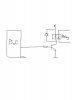
Hi. One of the technical specialists at Cypress gave me the attached schematic to communicate the CY8C24894 chip (data sheet attached) with a relay. The chip is on the PSoC in the schematic - which connects to a USB port. I’ve contacted them again asking for values for the four parts in the schematic. I’m wondering if someone might be able to answer the same question, and also take the time to explain to me what these parts are doing at these values.

Would the values of these parts likely have to be different for different chips?

Also, does anyone know of any example Java computer programs that can read analog pins on a CY8C24894 chip?

Do Java programs have to be different when communicating with different types of chips on peripherals, or can different types of chips read the same Java code?
 

Attachments

  • relay.jpg
    relay.jpg
    301.1 KB · Views: 110
  • DataSheet_CY8C24x94_C[1].pdf
    689.2 KB · Views: 121
Last edited:
Would the values of these parts likely have to be different for different chips?

The diode across the coil should be a switching type. The coil current and voltage decides which transistor to use. The resistor should pass base current >1/10 of coil current and this current should be < the chip output pin max current. If the same pin needs a valid logic signal for other circuitry, the pin voltage levels must be valid logic levels while supplying the 1/10 of coil current.
 
Last edited:
The diode across the coil should be a switching type. The coil current and voltage decides which transistor to use. The resistor should pass base current >1/10 of coil current and this current should be < the chip output pin max current. If the same pin needs a valid logic signal for other circuitry, the pin voltage levels must be valid logic levels while supplying the 1/10 of coil current.

Is coil current the same as load current? What does base current mean? The pins are analog output pins at 8.8mA and 5V. Can each part in the circuit have many different rating possibilities – depending on the other parts? Or, is there pretty much just one range of ratings that the parts must have to be connected together in this circuit?
 
Is coil current the same as load current?
It's the load current for the transistor (8mA, see below). The load current for the micro is the base current (0.8mA, see below). The ultimate load has current that goes through the relay contacts.
Relay 45-191 from Hosfelt.com has a coil current of 12/1500Ω = .008 A and switches 0.5A so it has a current gain of 0.5/.008 = 700. The relay load current is 0.5A.

What does base current mean? The current that must go into the base in order to get collector current to pull in the relay. Relays and transistors are current operated.

The pins are analog output pins at 8.8mA and 5V.
So to get a collector current of 8 mA and
assuming the 5v does not drop very much when it sources 8mA and
assuming a 1v base to emitter drop,
you need a base current of 0.8 mA and,
so (5-1)v/.0008A = 5kΩ for the resistor shown in your diagram.

Can each part in the circuit have many different rating possibilities – depending on the other parts?
Yes, they are mostly interdependent, so start at the load current and determine the rest of the parts from there. However, generic relay driver circuits may cover 90% of the applications. The ULN series ICs interface from microchips to loads like this.
 
Last edited:
Status
Not open for further replies.

Latest threads

New Articles From Microcontroller Tips

Back
Top