mod_critical
New Member
Hello all!
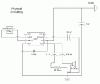
I am trying to build an audio system for an educational Kiosk that will be in use at the Soudan Underground Laboratory in Tower, MN, and I'm having some trouble with the fundamentals. I need to build a box that takes one input and has four independantly controlable headphone outputs and can be switched to output to one set of full range speakers. My first step for this was to build one LM386 based amp (the circuit I will be using for each cannel of the headphone outputs) and once I got that working move on to the loudspeaker amp, and then finally etch a board and build the case. Now with digital electronics I am quite accomplished, but I have not done much along the lines of amplification circuits before. When I built the LM386 circuit I did it on a breadboard using a design I found by Stephan Lafferty https://www.minidisc.org/headbanger.html. I had poor audio results with this (which at this point I'm sure has nothing to do with his design) so I built the reference design in the LM386 technical documents provided by National Semiconductor. I still had this hideous hum in the output so I scrolled the Internet searching for LM386 information. With the addition of a couple capacitors and through following some suggestions I found, I knocked out some of the hum. However, it is still louder than the desired audio, so it is hardly a fixed problem. I have used both 12v from my bench supply and a 6v wall-wart to power the thing. I have tried different audio sources, source cables, and output devices. Below is a schematic of my current design, and an illustration of how I have things connected. This project has violently put me in my place as a complete audio newb, and I am in severe need of an education. I am very greatful for any help anyone can offer, and thank you in advance!
Oh, By The Way: The 100k Pot isn't shown in the physical design because it isn't there at the moment, I have the trouble with or without it.
Schematic:
**broken link removed**
Physical Build:
**broken link removed**
It seems Visio numbers pins in a way different from the rest fo the world, on the right side of the LM386 chip, the pins should be vertically reversed, with 5 at the bottom and 8 at the top.