Continue to Site

Welcome to our site!

Electro Tech is an online community (with over 170,000 members) who enjoy talking about and building electronic circuits, projects and gadgets. To participate you need to register. Registration is free. Click here to register now.

  • Welcome to our site! Electro Tech is an online community (with over 170,000 members) who enjoy talking about and building electronic circuits, projects and gadgets. To participate you need to register. Registration is free. Click here to register now.

Simple LM383 Amp Help

Status
Not open for further replies.

mod_critical

New Member
Boy I must really be terrible at this :D ... I got that LM386 amp to work great (thank you very much john1)... but now my vexation is the amp for the loudspeakers.

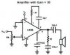
I built this design, from the page **broken link removed** under LM383 Power Amp. The schematic they provide is as follows:
**broken link removed**

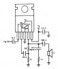
I turn the thing on and it works, well at first. As I turn up the input the volume from the speaker increases... but suddenly I hit a point where there is a tiny bit of distortion; the sound goes right to hell and the thing heats up considerably, even AFTER I turn the volume back down!! I let it sit turned off till its nice and cool again and then it sounds fine, and the process repeats. The chip dosen't get warmer as I turn up the voume, it simply spikes with heat at that point in turning up the volume. I built my circuit to the schematic above, my actual physical construction is shown below. If anyone can see anything wrong with this, I would be most greatful for your help! If all else fails, those loud speakers are gunna get the LM386 treatment :D -- but I would really like to feed them their 7 watt capacity to get some nicer sound for the Kiosk.

**broken link removed**

Once again thanks soo much in advance!
 
To avoid high frequency oscillation, don't leave the Zobel (Boucherot) components (serial 47nF,10ohm) from output.
 

Attachments

  • LM386_5.jpg
    LM386_5.jpg
    15.2 KB · Views: 1,155
Hi mod_critical,

Sorry i havent replied sooner, my e-mail server is down for
a while, it was only cos i looked in at the forums that i
saw your post.
I am glad that your amp is working ok now.

Your present problem with the 383 could be a few things,
you say it occurs when increasing the volume control past
a certain point, that sounds as though its bursting into
oscillation, or maybe instability through the supply.

I'm looking through some stuff about the 383 and if i see
any likely things to try, i will get back.

Maybe others have some suggestions,
best of luck with it,
John.

just noticed, Sebi also thinks its along these lines
john.
 
Hmm a bit more information. Per the document at http://www.btinternet.com/~netsurf/SudburyRC/coxamp.html under the section that reads:
Testing : Check before first power up that the resistance between -ve and +ve is high, and that there are no blobs of solder crossing tracks on the circuit board. When turned on, the normal power consumption of the LM383 is around 50mA +/- 10mA, regardless of supply voltage. If the amplifier starts to oscillate, you'll find that the current drawn will rise well above this to 500mA or more, and the chip will get very hot very quickly. If this is the case, turn off the power and check the decoupling of the power rails, input and output, and the decoupling capacitors

Fault Finding: If you end up with feedback in your circuit, check the +ve and -ve supplies for any AC noise using an oscilloscope. If you find any, your decoupling isn't working.

Anyway, I tested the current draw on the circuit, and I found that current draw went from about 50 to 60 mA as I increased input level, until that point where everythign goes to crap, then it jumped to 250 mA, and then wound down to about 120 mA where it sat and got hot.

The document I wupoted above mentions a problem with decoupling, and tracing oscillatioon with a scope. However I have no scope, and I don't know where to begin on any of these suggestions (fixing the decoupling). If this helps anyone point me in the right direction, I would be most appriciative! Thanks!
 
My National Semi audio handbook shows the input cap switched around with the '+' on the IC side.
It also shows a .2uf/1ohm Zobel (Boucherot) on Vout to ground.
"increased input level" from what? A 100k pot?
Everything grounded?
I build the National circuit version years ago and remember it working fine.
 

Attachments

  • lm383.jpg
    lm383.jpg
    30.8 KB · Views: 709
Yaa, that series resistor/capacitor to ground was not on the reference design I built. I saw that on a number fo other designs, and have added it to mine. Now the audio still wigs out at the same point it did before, however with that resistor and capacitor in there, it stabalizes and does not remain in oscillation. The point at which the audio becomes distoreted though, it is actually quite loud. I guess I was just expecting more out of those full range speakers than I should have. The way the design is now will be fine. The audio still becomes unstable at a point, but it dosen't need to be turned off and sit for 5 mintes to get back to normal like before :D --- anyway I was adjusting the input by adjusting the volume on the headphone output of the radio I'm using to test.

Thanks for your help! And for everyone that has read this, thank you for your time! I'll be etching the board tomarrow morning, so if anyone has a suggestion to improve performance before then, please do post! I'll try it tonight. As for now I need some R&R, I was in this lab till 4:30 this morning picking away at this :roll: .

Thanks again everyone!
 
Hi mod_critical,

I've been having a bit of a look at some of this stuff, and
that page you posted is well worth a good look.

From:
http://www.btinternet.com/~netsurf/SudburyRC/coxamp.html
"
A critical part of the amplifier design is to ensure the 100nF
/ 1ohm combination is as close as possible to the output of
the amplifier. These two components effectively surpress any
ambitions the LM383 has of becoming a high frequency
oscillator - which this amplifier chip has a nasty tendency of
doing. If it does oscillate, you will find that the amplifier
will start drawing 500mA from the batteries, and the heatsink
tab will get hot very quickly - confusingly, it may also be
working well as an audio amplifier, so making troubleshooting
difficult. If you have problems with this, try increasing the
value of the decoupling capacitors on the +ve supply to the
amplifier, and make the 100nF capacitor bigger on the output -
ensure you use a low inductance capacitor for this, such as a
Polystyrene one."


This is from that post earlier, and it seems to confirm that
the problem is some sort of feedback causing oscillation,
the site this came from explains pretty well what can happen,
and how to deal with it.

The reason that two capacitors in parallel are used on the
output is because the way the layers are wound on can give
a small inductive effect, so another tiny cap is often put
across it, to make sure the higher frequencies are effectively
shorted to ground. These frequencies are way above the audio
range, and should not have any affect on the audio output.

The 'de-coupling' of the earlier stages will almost certainly
clear your problem, if its working properly. What this does
is to take a feed from the supply thats feeding the output
amp, and feed it to the pre-amp through a resistor, and put
a smoothing capacitor so that ripples and changes on the
supply to the pre-amp are smoothed, and hopefully dont find
their way into the signal path.

If you dont have any de-coupling between your pre-amp and
your output amp, that would explain this problem.
If you do have, then maybe it needs looking at.

Also, the 1 ohm and 0.2 mfd at the output should be very
close to the output terminals on the chip.

That site also shows that he has included small capacitors
across the smoothing caps in the power supply, and at the
de-coupling, a worthwile precaution i think.

I doubt if i would start making the PC board till i was
quite happy with the loose-wired prototype, and i would
most likely stick to the same components when making the
final item, i have had things go wrong just cos parts werent
quite the same, even though they were marked the same.

Please come back and let us know how you're getting on.
Best of luck with it,
John
 
Follow Up

Hey guys! Just a follow up! Got this sucker built, from concept to the box in the pics in just five days! And I was able to do that beacuse of all your help; Thanks again, everyone!

Board:
**broken link removed**

Box:
**broken link removed**
 
Status
Not open for further replies.

Latest threads

New Articles From Microcontroller Tips

Back
Top