checkmate said:
........Therefore, their specifications often come with a maximum forward current (max If). If you know these specs, the resistor provided can simply be calculated using simple ohm's law.
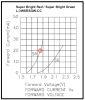
HE Red
Forward voltage at IF=20mA: 2.5V
Forward current max.: 30mA
Reverse voltage max.: 5V
Wavelength @ peak IF=20mA: 627nm
Power dissipation PT: 105mW
Light output min.@ 20mA: 12mcd
Light output typ.@ 20mA: 40mcd
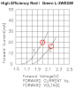
Green
Forward voltage at IF=20mA: 2.5V
Forward current max.: 25mA
Reverse voltage max.: 5V
Wavelength @ peak IF=20mA: 565nm
Power dissipation PT: 105mW
Light output min.@ 20mA: 12mcd
Light output typ.@ 20mA: 35mcd
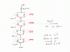
So using my newly aquired skill in working out the resistor required:
r=(12v-(2.5v*4))/25mA
so r = 80 Ohms which according to my chart I found for working out pretty colour codes means I need a 'black - grey - black - doesn't really matter' resistor for each starting point of each line in series.
Is that right?
Ah, they don't do a 80Ohm so need a 82 Ohm which is 'black grey red and whatever'