Continue to Site

Welcome to our site!

Electro Tech is an online community (with over 170,000 members) who enjoy talking about and building electronic circuits, projects and gadgets. To participate you need to register. Registration is free. Click here to register now.

  • Welcome to our site! Electro Tech is an online community (with over 170,000 members) who enjoy talking about and building electronic circuits, projects and gadgets. To participate you need to register. Registration is free. Click here to register now.

Simple LED question (definately leading to more)

Status
Not open for further replies.

angie1199

New Member
Hi all

I know nothing about electronics. So now you know where you are with me.....

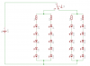
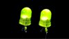
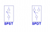
I have a 12V DC pwr supply (not sure of the ampage it's got (or whatever the correct term is) and I want to power a number of LEDs from it. The LEDs will be 2 colour, and when a switch is changed the other colour will light up (glow or whatever LEDs do)

I've looked on google and all the circuit diagrams I can find tell me is I need a resistor to stop the LEDs blowing. And most of the circuits either use battery power or are for flashing LEDs, neither of which I want as an end result.

Please help.

Angie
 
a resistor is needed to take the access voltage (ie power)

an LED (basically a diode) when it conducts has a voltage that is developed across it, there is a fancy formula to calculate it (or you look at the datasheet), but for now we will say 1V

The brightness of the LED is related to how many amps you force through the LED. More amps brighter, even more amps and POP

So say you have a 12V battery and you connect an LED straight across it, that LED when it conducts should ONLY have 1V across it, you are forcing it to have 12V and it goes BANG!!!!


reason? well if you look at the volt-amp curve of an LED you would see that the current increases with increase forward voltage. For 1V it would be say 20mA, for 12V it would end up being in the order of 100's of amps


So what are you going to do with the extra 11V from the battery? well use a resistor to drop the voltage

V = IR, thus R = V/I
V = 11V
I = 20mA
thus you would need a resistor of 550R and it would dissipate 220mW of power.


So you have 2LED's in series the voltage is now 2V (treat it as one big LED)

Battery is 12V, LED drop is 2V thus the voltage for the resistor is 10V
V=10V
I =20mA (you still want the same current for the same brightness)

thus R=500R


So that is LED's


in its simplest form what you would do is have the battery have a resistor on it (value you need to calc depending on yr LED's and how much current you want). Then a single throw, double pole switch to allow the change over to two different LED-branch colours
 
Yes, you need a resistor in series with the LED (or LEDs) to prevent the LED from blowing and to set the brightness to the level you need.

Use a circuit that has a battery and replace the battery with your power supply. If the circuit was designed for say a 6 Volt battery, then you will need a larger resistor for 12V in order to limit the current to about the same value.

As a rough rule of thumb, and assuming the battery is 6V, double the resistor value and add a bit. So, for example, if the resistor is 470 Ohm, then use a 1200 Ohm.

If you search this forum for "LED" you will find plenty of info. including formulae for calculating the current. It is very easy when you know how, but I won't start writing maths at this point to avoid confusing you.
 
Styx posted his reply while I was typing the one above. I agree with his response except that LEDs have more than 1 V dropped across them. A red LED drops about 1.8 V and other colours generally drop a bit more.
 
Ok, thanx to both of you. So now I get it, a resistor doesn't lower the amps it lowers the voltage. So there's no need for a voltage regulator or lowerer (whatever)

Now Styx mentions two in series. I'm going to need a few more than that (something like 20) so if each one needs 2.2v (maplins 3mm leds) then in theory I'd need a 44V power supply.... Is this right??????

If this is correct then I think I'm in trouble.....

Also the LEDs are bi-color so how do I get the change in colour?

<mutter - give me a house to rewire anytime but small stuff!!!>

Angie (sorry for being a pain)
 
Do your LEDs have 2 leads or 3? Do you have a part number, or specifications of recommended current and forward voltage?
 
angie1199 said:
Ok, thanx to both of you. So now I get it, a resistor doesn't lower the amps it lowers the voltage. No, the resistor reduces the current (the Amps). The voltage is determined by the current through the LED as Styx wrote. So there's no need for a voltage regulator or lowerer (whatever) Correct

Now Styx mentions two in series. I'm going to need a few more than that (something like 20) so if each one needs 2.2v (maplins 3mm leds) then in theory I'd need a 44V power supply.... Is this right?????? No you can connect them in series parallel. Ignore the bicolour question for the moment. For single colour LEDs you would connect 4 is series with a resistor. 4 * 2.2 = 8.8 Volt. If you set the current to say 10 mA then the resistor would be (12 - 8.8 )/10 = 0.32 k. So use 330 Ohm. So for a total of 20 LEDs, you will need 5 strings of 4.

Also the LEDs are bi-color so how do I get the change in colour? You need to answer Ron's question before we can answer this one.
 
I don't think UK's Maplin nor Taiwan's Kingbright know what kind of Bi-Colour LEDs they have.
Their description for the L937 series states 3 leads with one as common but the physical dimensions and schematic show only two.
Of course, each colour has a different voltage.

Four of the 1.9V red/2.2V green ones in series with a 180 ohm resistor will provide 24.4mA for red and 17.8mA for green "if" the voltages are what they say. Swap the polarity with a DPDT crosswired switch to change the colour.
 
You could balance the current by connecting the switch described by Audio to select a different resistor
 
Hi Len,
I can't remember if the green appears brighter than the red or is dimmer.
They don't have the same current nor efficiency and your eyes respond differently to their colours anyway. Bi-Colour LEDs are probably made to appear with the same brightness from a single resistor.
 
ljcox said:
Styx posted his reply while I was typing the one above. I agree with his response except that LEDs have more than 1 V dropped across them. A red LED drops about 1.8 V and other colours generally drop a bit more.

yer I know they have more drop (1.2V is my rule of thumb) but 1V was more for my easy maths ;)
 
Ok guys, the ones I want to use are GW62S (the coloured photo not the three opaque ones shown in the search result)

The problem I see (and obviously I'm open to correction) is if I have four in series x four strings, then how do I change the colour of just one of the LEDs in one string?

The end result in a display showing which doors are open and which are closed. Total of about 20 doors. I want the green on when the door is closed and the red on when the door is open.

Again, thanks for trying to help me

Angie
 
angie1199 said:
Now Styx mentions two in series. I'm going to need a few more than that (something like 20) so if each one needs 2.2v (maplins 3mm leds) then in theory I'd need a 44V power supply.... Is this right??????


well I mentioned 2 in series as a demo point (sine no other info given at the time).
So you need 20 and a rough guess state you will need 44V volts JUST to bias the LED's on (remeber you will need the volt drop of the burn-resistor as well)

The only other way then is to parallel the Diode's up. THis has a risk as each one might not share the current equally BUT it means that the voltage at the LED's would be 2.2V for 20 and not 44V

A compromise would be to do a series-parallel arrangement. Parallel to get the volt-drop down, series to increase the voltage so the burn resistor is lower
 

Attachments

  • cct_137.png
    cct_137.png
    7.1 KB · Views: 576
It will take a lot of fancy switching to put in series 3-wire bi-colour LEDs.
You need 2-wire LEDs to easily do what you want.

Or you could use a 3V power supply and a series 39 ohm current-limiting resistor for each bi-colour LED. Power both red and green when the doors are moving for yellow.
 
angie1199 said:
Ok guys, the ones I want to use are GW62S (the coloured photo not the three opaque ones shown in the search result)

The problem I see (and obviously I'm open to correction) is if I have four in series x four strings, then how do I change the colour of just one of the LEDs in one string?

The end result in a display showing which doors are open and which are closed. Total of about 20 doors. I want the green on when the door is closed and the red on when the door is open.

Again, thanks for trying to help me

Angie
I don't think you want to put them in series if you want to change individual colors.
Can you clarify whether this is device has 2 leads, or 3? I didn't find the picture you were talking about. Perhaps you can post a link to the picture.
 
Hi guys

I'm thinking this may be impossible :)

Here's the link for the LED
**broken link removed**
 

Attachments

  • 35740i0.jpg
    35740i0.jpg
    10.7 KB · Views: 483
angie1199 said:
Hi guys

I'm thinking this may be impossible :)

Here's the link for the LED
**broken link removed**
It's not impossible. However, you hopefully have learned here that you can never supply too much information. It seems like we have had to drag it out of you, but I realize that it is difficult for you to anticipate what we need to know.
So, another question: What sort of door open/closed sensors do you have, if any? Switches, maybe? If so, what kind of switches?
 
Hi Ron,

Ok, contact with the green annode (is that right) will be disconnected when the door is open and at the same time contact to the red is made.

So as far as I can see this is the same as having a straight forward 2 way toggle switch with no off position (I've used them before)

Would this be easier with small (3mm dia 8.5mm long) bulbs instead of LEDs? Either works good for me....

Agie
 
angie1199 said:
Hi Ron,

Ok, contact with the green annode (is that right) will be disconnected when the door is open and at the same time contact to the red is made.

So as far as I can see this is the same as having a straight forward 2 way toggle switch with no off position (I've used them before)

Would this be easier with small (3mm dia 8.5mm long) bulbs instead of LEDs? Either works good for me....

Agie
I gather from this that the doors currently don't have switches (or something) that will sense when they are open or closed, and you will have to add them. Is that true? We need to know if your switches will be SPST or SPDT. SPST (single-pole, single-throw) is either open or closed. SPDT (single-pole, double-throw) is closed to one or the other of the two "throws". Either can be made to work (I think), although SPDT is more versatile.
 

Attachments

  • switches.png
    switches.png
    5.1 KB · Views: 456
angie1199 said:
The problem I see (and obviously I'm open to correction) is if I have four in series x four strings, then how do I change the colour of just one of the LEDs in one string? This could be done, but you would need DPDT switches on each door

The end result in a display showing which doors are open and which are closed. Total of about 20 doors. I want the green on when the door is closed and the red on when the door is open. What type of switch do you intend to use on each door? SPST, SPDT, DPDT?Angie

If you answer these questions and the ones Ron H asked, then we can help you.
 
Status
Not open for further replies.

Latest threads

New Articles From Microcontroller Tips

Back
Top