Continue to Site

Welcome to our site!

Electro Tech is an online community (with over 170,000 members) who enjoy talking about and building electronic circuits, projects and gadgets. To participate you need to register. Registration is free. Click here to register now.

  • Welcome to our site! Electro Tech is an online community (with over 170,000 members) who enjoy talking about and building electronic circuits, projects and gadgets. To participate you need to register. Registration is free. Click here to register now.

Simple LED grid backlight

Status
Not open for further replies.
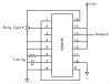
The most efficent way to dim LEDs is to use a pulse width modulator, look up SG3524 and other chips in that series. This will dim the LEDs but not drain the battery. If you use a resistor to dim the LEDs you are wasting power as heat and making the circuit less efficent.
 
Or you could use switches to only turn on part of the array and not have to worry about PWM'ing it at all =)
 
Audio, is that true I would still need to test every LED even if I know the LEDs I have are the same ones I linked a spec sheet to in a prior post? What is the variable, current? I hooked those LEDs up with 3 new energizer batteries without resistors and it worked great but after being educated that shouldn't work, and I don't want to have the possibility of blowing the LEDs every time I switch out the batteries.

Sceadwian, the issue I have with the switches is that I am using this grid (4x4) as a back light. The light would have hot spots and low spots without all the LEDs lit at the same time. Best case scenario would be being able to dim the LEDs to what is needed, and thus save battery life by only using what is needed.

Alex, I looked up a data sheet for the chip you mentioned and the cost seems reasonable. How is it hooked up and what other components are required?
 
If you need them all on the best + simplest (and cheap) solution for variable power is a 555 timer. The closer the driving voltage is to the LED's voltage the more variable their current use is going to be as the battery discharges and it's voltage sags, this is why constant current sources are used.
 
Alex, I looked up a data sheet for the chip you mentioned and the cost seems reasonable. How is it hooked up and what other components are required?

You are going to need a potentiometer to control the duty cycle and a capacitor and resistor for the internal oscillator.

Use pin 14 as the output to the LEDs or use it to drive a larger power transistor depending on your power needs.
 

Attachments

  • SG3524 PWM.jpg
    SG3524 PWM.jpg
    37.9 KB · Views: 131
A555 is far simpler and far cheaper for such a simple application, it also has half the pin count/size
 
The LEDs are probably not 3.6V because their max voltage is 3.6V and their typical voltage is 3.2V.
Their actual voltage might be only 3.0V since the minimum voltage is not spec'd.

Their current must be limited or regulated.
 
Status
Not open for further replies.

Latest threads

New Articles From Microcontroller Tips

Back
Top