Continue to Site

Welcome to our site!

Electro Tech is an online community (with over 170,000 members) who enjoy talking about and building electronic circuits, projects and gadgets. To participate you need to register. Registration is free. Click here to register now.

  • Welcome to our site! Electro Tech is an online community (with over 170,000 members) who enjoy talking about and building electronic circuits, projects and gadgets. To participate you need to register. Registration is free. Click here to register now.

Simple LED circuit

Status
Not open for further replies.

Plungestep

New Member
I'm trying to build a simple LED circuit that activates when a piezo detects a knock or bump. The LEDs are standard red LEDs.

Is there a specific transistor I should be using here?

**broken link removed**
 
Do you want the bump pulse duration threshold to be selectable or calibrated
Also pulse duration to be stretched so it is more visible? say from 1ms to 100ms
then more features must be added.

Is this to detect something fragile from damage?
 
You do not know the polarity of the piezo pulse output which might be positive which will turn on the transistor for such a short duration that you might not see the LEDs light, or it might be negative that will destroy the transistor. So a pulse-stretching circuit should be added and a diode is needed parallel with base and emitter.

The output current from a piezo is very low unless it is smashed hard so the transistor might not produce enough current in the LEDs to be seen. Maybe a darlington transistor or an opamp should be used instead.

Look in Google for E-Drum Circuit. They use a piezo mounted on the skin of a drum and the low current output of the transistor drives another circuit. Some of the e-drum circuits shown DO NOT WORK.
 
This is supposed to be a simple, inexpensive circuit to light up when a drum head is hit. It must turn on fast enough to light the LEDs for a very brief period of time, especially when the drummer is hitting the drum very rapidly. Keeping this simple and low cost is key here.

Any suggestions or improvements would be appreciated!
 
This circuit wont work due to impedance gain during saturation is too low. I gave you clues in other similar threads.
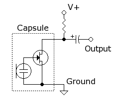
Electret mic with bias voltage
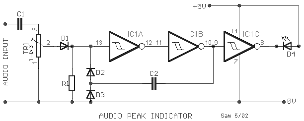
Signal amplifier using CMOS inverter
Mono-preamp-based-on-CMOS-IC.jpg

Diode detector using CMOS inverter
Schmitt trigger using CD40106B Schmitt inverters or use two CD4069 with R ratios to act as Schmitt with hysteresis.

This is one of many ways.
audio-peak-indicator_orig.gif

MOSFET after CMOS to drive LEDs with suitable 10x current rating.


CD4049 chip.
**broken link removed**
 
Last edited:
THe simplest possible might be this.

Using R= 36k V+=9V C= 10uF with diode shunt to clamp negative voltages. and a 100K R to ground to a Nch MOSFET Gate
Electret Mic below with 2 external parts using 36K should be able to create >1V peak with mic attached to pedal drum. Polarity of pulse needs to be verified by checking sensitivity of mount vs inverted mount, but in any case , pulse will ring so either polarity will work.
Electret_condenser_microphone_schematic.png

THis MOSFET comes in SMT only but triggers from 0.9V and can easily switch 2 amps. You would replace your transistor with this one and use diode clamp with mic out to series cap with 100K to ground on gate to source.
**broken link removed**

a simple result as follows.
upload_2015-8-14_16-10-52.png
 
Last edited:
The capsule is the typical tiny Electret mic which contains an open drain FET to amplify the signal into Rload. Cost $0.25 in some places.
mic_section_med.jpg


Electret_condenser_microphone_capsules.jpg
 
I still think this can be done with a piezo. A microphone is of no use when there are 5 other drummers playing next to you, and each drummer has 4 drums they are playing. If you want to light each one individually, you need some sort of isolation. A microphone won't cut it, it will need to be a piezo taped to the drum head.
 
I designed a chaser with variable speed for a buddy who is a pro musician and I added the electret mic feature for the drummer to sequence the lights on the the sign with each letter of the bands name.

We had to tape up the mic pretty good then next to the drum had no false triggers. A piezo or even a ceramic cap could be used for that matter.
 
Simply look in Google Images for E-Drum Circuits to see them mount a piezo transducer (not a piezo beeper) on a drum and the amplifier circuit it uses.
 
Status
Not open for further replies.

Latest threads

New Articles From Microcontroller Tips

Back
Top