Continue to Site

Welcome to our site!

Electro Tech is an online community (with over 170,000 members) who enjoy talking about and building electronic circuits, projects and gadgets. To participate you need to register. Registration is free. Click here to register now.

  • Welcome to our site! Electro Tech is an online community (with over 170,000 members) who enjoy talking about and building electronic circuits, projects and gadgets. To participate you need to register. Registration is free. Click here to register now.

Simple clock.

Status
Not open for further replies.
Hi, thanks.

Im sure I have connected it for produce the BCD count, here is the draw and Im sure I have connected all in that way at the stage that I already have in memory the pins connections...


Now the timer is in asstable mode, I take the diagam from here **broken link removed** , I setup C1 = 10uF, R1= 2K R2= 71K

Time High = 0.693 * 10uF * 71K = 0.49203
Time Low = 0.693 * 10uF * (71K+2K) = 0.693 * 10uF * (73K) = 0.50589

That is the output of the timer that I pass to pin 14 or C0.


Im reading some like the minimung frequency and I guess there is where my problem are??????

There is a minimun of 32MHz for CP0 and 16 Mhz for CP1 ..... havent taked this in care... :S... is that the source of the problem????, I have watched a clock in internet that use this 7490...

What you think???
 

Attachments

  • conf.jpg
    conf.jpg
    12.6 KB · Views: 625
I see is like the minimun for the max frequency....

Then for what it cant count, the model I have a "f" above the number DM74ls90N, the only requisite for count in BCD is connect Q0 to the pin 1 :S, then I dont understand, some times when I reset (change the cable manually of the reset to Vcc and then to Gnd or only disconnect it from Gnd) I cant get it to count 0, 1, 2 , 7, 8, 9.

Where are 3, 4, 5 and 6 ???? :S I dont understand :(. Or Im to noob for electronics??? :S
 
AAAAAAAAAAAAAAAAAAAAAAAAAAAAAAAAAA
aaaaaaaaaaaaaaaaaaaaaaaaaaaaaaaaa
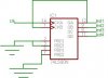
Its alive!!!!!!!


By the way, havent changed any connections (I remember that I disasemble and assemble it more than one time and much checking in the connections :S).

Remember that I say have old adapter and that have power ups and down, I have solucionated that connecting a capacitor of about 10 uF to Vcc and Gnd (by a sugestion of my brother).

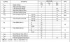
After see that some times that old adapter even turn on and I need to move it for turn on, I decide to buy a new one (12, 9, 7.5, 6, 4.5, 3 I have measured directly when is at 3 and the multimeter say 5.5V ;)), anyway now come to mind what will happend if I connect the same capacitor to this new adapter, to Vcc and Gnd and tada is working!!!!!


Hahahaha, exactly dont understand for what is now working, but the capacitor if I remember correctly hold Volts then I need more Volts for this circuit or is only I need them more continuos???

Now is time to continue to the next part ;) :D
 
good for you !!
or is only I need them more continuos???
this is probably the reason..
dont go much more than 5.5 V , you are at the upper limit , of the allowable voltage for the chip..
is it possible to use batteries ?
 
That is the problem of the new adapter :S, it say 3V in the text, but its 5.5V, pehraphs I will make a Voltage divisor, also I will put the capacitor for have a more stable input :D.

Yes, is posible use batteryes, but I need buy them and the get carrier for make it more easy I guess :).


By the way, if I make the voltage division, how many Volts will be OK? 5V? for example the ne555 say from 4.5 to 16.
 
a voltage divider is a good idea , but you may find that it does not work as planned.. .. ie use it just for the 7490 , let the Leds and the 555 run off the 5.5 V supply..
 
Status
Not open for further replies.

Latest threads

New Articles From Microcontroller Tips

Back
Top