Hi people, this is the first time I try make a circuit.
I have selected the 7490 for do a clock that count hours, minutes and seg.
h2h1:m2m1:s2s1
My idea is this one, have a function that detect when s2=5 and s1=9 that launch the clear and also pass a pulse to the next "phase", also when in a unit is detected X1=9 it will pass a "pulse" to X2.
I dont have for the moment the timer for pass the pulse, then Im doing it manually, ie, with unplug/plug a cable to Vcc.
I dont know if that matter.
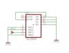
The next is the connections that I have done: the first number is the pin, I have abreviated connected to with ->
1 -> 12
2 -> Vcc
3 -> Gnd
4
5 -> Vcc
6 -> Vcc
7 -> Vcc
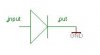
8 -> LED -> Gnd
9 -> LED -> Gnd
10 -> Gnd
11 -> LED -> Gnd
12 -> LED -> Gnd
13
14 -> plugable/unplugable cable to Vcc
I think that pheraphs the problem is that I dont have a counter??? and Im using the connect/disconnect the cable in the pin 14???
If is that, I have watched an astable configuration at this place **broken link removed** and have calculated this values:
c1 = 10 micro Farads
r1 = 2K Ohm
r2 = 70K Ohm
I dont know if there exist suchs resistors is that right?
If some one can check if my connections are right? for generate a BCD count... I think that what I have in mind for pass a "pulse" to the next unit and reset then when I get 59 is what I whant, but Im unable even to generate the BCD count , some one?
I have selected the 7490 for do a clock that count hours, minutes and seg.
h2h1:m2m1:s2s1
My idea is this one, have a function that detect when s2=5 and s1=9 that launch the clear and also pass a pulse to the next "phase", also when in a unit is detected X1=9 it will pass a "pulse" to X2.
I dont have for the moment the timer for pass the pulse, then Im doing it manually, ie, with unplug/plug a cable to Vcc.
I dont know if that matter.
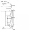
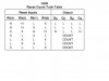
LS90
A. BCD Decade (8421) Counter — The CP1 input must be externally
connected to the Q0 output. The CP0 input receives
the incoming count and a BCD count sequence is produced
The next is the connections that I have done: the first number is the pin, I have abreviated connected to with ->
1 -> 12
2 -> Vcc
3 -> Gnd
4
5 -> Vcc
6 -> Vcc
7 -> Vcc
8 -> LED -> Gnd
9 -> LED -> Gnd
10 -> Gnd
11 -> LED -> Gnd
12 -> LED -> Gnd
13
14 -> plugable/unplugable cable to Vcc
I think that pheraphs the problem is that I dont have a counter??? and Im using the connect/disconnect the cable in the pin 14???
If is that, I have watched an astable configuration at this place **broken link removed** and have calculated this values:
c1 = 10 micro Farads
r1 = 2K Ohm
r2 = 70K Ohm
I dont know if there exist suchs resistors is that right?
If some one can check if my connections are right? for generate a BCD count... I think that what I have in mind for pass a "pulse" to the next unit and reset then when I get 59 is what I whant, but Im unable even to generate the BCD count
, some one?