Continue to Site

Welcome to our site!

Electro Tech is an online community (with over 170,000 members) who enjoy talking about and building electronic circuits, projects and gadgets. To participate you need to register. Registration is free. Click here to register now.

  • Welcome to our site! Electro Tech is an online community (with over 170,000 members) who enjoy talking about and building electronic circuits, projects and gadgets. To participate you need to register. Registration is free. Click here to register now.

Simple circuit issue

Status
Not open for further replies.

totempole

New Member
Hi,

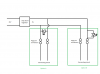
I need the LED to light up every time the "connecting circuit'" is connected to the main power supply. In option A the LED would never turn off and in option B the LED causes a voltage drop over the pogo pin connectors. Option B causes the voltage to drop from 5V to 2.66V, which is too much. Actually any voltage drop that causes the voltage to drop lower than 5V over the pogo pin connectors is not acceptable. What are the methods to achieve the desired function? Any help will be appreciated.

Kind regards
Michael Mullineux
 

Attachments

  • Charging indicator light issue.png
    Charging indicator light issue.png
    9.9 KB · Views: 206
Actually, you need a current limiting series resistor for each LED....and probably new LEDs if you're used the circuit as shown.

If you use a 1k resistor, the LED will draw about 3mA.
 
What are the maximum and minimum currents that the connecting circuit takes?

You will need some sort of amplifier if the voltage drop on an LED is too much.

Hi Diver300,

The maximum current is 1A and the minimum i suppose is just above zero, the 'connecting circuit' is battery with a charge controller. Id say the average is between 0.5 and 1A.

Can you tell me why you need this info to answer my question.

Kind regards
Michael Mullineux
 
Actually, you need a current limiting series resistor for each LED....and probably new LEDs if you're used the circuit as shown.

If you use a 1k resistor, the LED will draw about 3mA.

Hi Visitor,

Im not using any resistor, also if i use a different LED the resistance might reduce but not enough to stop the voltage drop dropping enough to stop the supply voltage dropping below 5V. what i need is someway to connect the LED in parallel but only allowing it to 'turn on' once the connecting circuit is connected.

Kind regards
Michael Mullineux
 
Keep in mind the LED is a current driven device. LEDs have specifications which include a Vfwd (forward voltage) and Ifws (forward rated current). Your option A will load the 5 volt supply as you observed. The LED needs a series resistor to work and limit the current through it. You need to provide your LED specifications? With a Vfwd of 1.2 V and Ifwd of 20 mA we get Vsupply 5.0 - Vled 1.2 = 3.8 volts / .020 Amp = 190 Ohms so about an off the shelf 210 Ohm series resistor. This will only tell you if voltage is present.

Ron
 
Hi Visitor,

Im not using any resistor, also if i use a different LED the resistance might reduce but not enough to stop the voltage drop dropping enough to stop the supply voltage dropping below 5V. what i need is someway to connect the LED in parallel but only allowing it to 'turn on' once the connecting circuit is connected.

Kind regards
Michael Mullineux

Current-limiting series resistors are not optional as Ron has explained.
 
Keep in mind the LED is a current driven device. LEDs have specifications which include a Vfwd (forward voltage) and Ifws (forward rated current). Your option A will load the 5 volt supply as you observed. The LED needs a series resistor to work and limit the current through it. You need to provide your LED specifications? With a Vfwd of 1.2 V and Ifwd of 20 mA we get Vsupply 5.0 - Vled 1.2 = 3.8 volts / .020 Amp = 190 Ohms so about an off the shelf 210 Ohm series resistor. This will only tell you if voltage is present.

Ron

Hi Reloadron,

I understand that but that is not my question, I need to wire the circuit in such a that the 5V supply doesnt drop when it gets to the pogo pin connectors. the only way to do this is to connect the LED in parallel but if i connect it in parallel it will always be on. how do i connect it in parallel but only get it to turn on if the 'connecting circuit' is connected?

Kind regards
Michael Mullineux
 
To detect when the load is connected you have to detect current through the wire NOT voltage between the wires. In drawing A there will always be 5 volts between the wires. In drawing B you have the LED shorted out. If you did not have the LED shorted out it would light when there was a load on the output BUT the voltage to the load would only only be about 3.2 volts assuming that it was a red LED which gives a voltage drop of about 1.8 volts. You will need a resistor in the circuit and sense the voltage across it. If this resistor is after the voltage regulator then the voltage to the load will be somewhat less then the 5 volts from the regulator. As you can't tolerate any voltage drop here you will need to detect the current between the unregulated power supply and the input to the 5 volt regulator. For this solution you will need to take into account that there will be a small current into the regulator even when there is no load on it's output. If you used a very low value resistor on the regulator output you would have a very small voltage drop but you would need an op amp to detect the very voltage drop across the resistor.

Les.
 
Last edited:
Hi Les,

Thanks so much for the input. I didnt quite follow what you are saying about the unregulated part, could you draw a circuit diagram? I need each LED to come on only when its corresponding connecting circuit is connected. Could the attached circuit diagram work?

Kind regards
Michael Mullineux
 

Attachments

  • IMG-20200323-WA0007.jpg
    IMG-20200323-WA0007.jpg
    97.6 KB · Views: 189
Could the attached circuit diagram work?
No, the attached diagram will illuminate the LED whenever the 5 volt supply is present. I have no idea what the symbol is preceding the LED? If you want to know if current is being drawn by a load there is more to it starting with how much current?

Ron
 
Hi Ron,

The symbol preceding the LED is a transistor I have a TIP120, will it work if I wire it in the way attached?

Kind regards
Michael Mullineux
Charging indicator light solution.png
 
No. If we figure the connecting circuit will draw any current then that could be worked into a scheme. Next if the LED and a series resistor were moved downstream of the pogo pins a LED would tell you that the 5 volt supply was present at that point. Again, the LED needs a current limiting resistor or about all it will do is cook and load the 5 volt supply.

Ron
 
Hi Ron,

The LED that I am using is called a DHG lilypad and has a resistor wired in series on the PCB. Does that solve the issue in my last circuit diagram?

Kind regards
Michael Mullineux
 
If the resister was a suitable value it would solve the problem of destroying the LED with excessive current but it dos not solve the voltage drop (About 0.6 to 0.7 volts.) through the base emitter junction of the transistor. Also with a small transistor the current through the base emitter junction would destroy the transistor.
EDIT. I have just noticed that the transistor you plan to use is a TIP120. As this is a darlington transistor the voltage drop across the base emitter junction will be between 1.2 and 1.4 volts. It does have an absolute maximum base emitter current of 120 mA so it would be safe to use with a load up to about 90 mA.

Les.
 
Last edited:
If the LED has a built in series resistor and if the LED is designed for 5.0 Volt use the LED as shown across 5.0 Volts will glow regardless of what is below the pogo pins. It will be always on. To turn the LED on when there is a load, yes, a transistor can be used but you need a means or way to detect the load and turn on the transistor.

Ron
 
Hi Ron,

The LED PCB can handle the 5V. I have set it up as per my last circuit diagram the problem is that the voltage drop is 1.36v over the pogo connectors when I connect the connecting circuit. the circuit can handle a maximum of 0.8v drop over the pogo pin connectors. Is there any way I can make this circuit work?

Kind regards
Michael Mullineux
 
Use a comparitor for your pogo pin power sensor.

LM393 works fine. It will work by powering with 5v but it is likely better more correct) o power it with your 21V unregulated source so the 5v input is not too close to the power rails.

As the load draws current, the current sensing resistor (0.1 to 0.33) for 50mA load. You can use smaller but you'll have to calculate thecurrent sense resistor size to get about 50mV to 100mV. Also, be sure to calculate the heat (watts) if you have a high current load.

images below are for disconnected and connected states.

D42FFC74-796E-403B-9E9B-4E6BE40E0D7C.png
5BB2CAE1-6A44-4449-80A3-459F1999A547.png
 
Last edited:
How much current can you source? Just for example in the above drawing the LM7805 regulator can supply 5.0 volts at 1.0 amp. In the circuit the load is 50 Ohms so we can figure 5 volts / 50 Ohms = 0.1 amp. Long as your source is capable of supplying the load that circuit makes for a nice solution. This isnot quite as simple as having an LED. :)

Ron
 
This is not quite as simple as having an LED. :)

Ron
I think the song goes...
"If it were easy as fishin' you could be a musician an electrician"
 
Last edited:
Status
Not open for further replies.

Latest threads

New Articles From Microcontroller Tips

Back
Top