Hi guys,
Im new here and new to electronics, but I've run into this problem before. What my experience has been is that the 555 gives out a sine wave form, not a square form. What that means is that it doesnt go all the way down to 0v, so there is still some residual power going to the NPN, causing it to allow current to flow through.
To solve this, you need to up the resistor value from the output pin. I have had good luck with both 16k and 18k resistors, as used on different circuits. Also, you will need to have another resistor connecting from post resistor to base to the emitter. This resistor needs to be about 10x the pin 3 to base resistor. This also helps drain the residual energy.
On my last flashing LED project, the LEDs were supposed to flash, then switch sides, flash, switch sides, etc. The no longer flashed, just changed sides. I tracked that problem down to not having the base to emitter resistor in place.
I hope I helped.
Clayton

 but i think that it shows how its all connected.
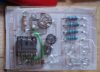
")
") .
.  After a while of debugging, when the list of 'things that could be wrong' starts to diminish, it can just take up too much time, which could be spent making another PCB. Still, if you're anything like me, its not the fact you need the board, its more just finding out why it doesn't work, for peace of mind (so rare these days..).