Continue to Site

Welcome to our site!

Electro Tech is an online community (with over 170,000 members) who enjoy talking about and building electronic circuits, projects and gadgets. To participate you need to register. Registration is free. Click here to register now.

  • Welcome to our site! Electro Tech is an online community (with over 170,000 members) who enjoy talking about and building electronic circuits, projects and gadgets. To participate you need to register. Registration is free. Click here to register now.

simple 555 4-LED Strobe light PCB problems.

Status
Not open for further replies.

bitem2k

New Member
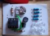
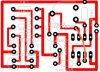
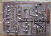
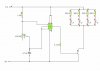
Im trying to design a PCB to make a simple 4-led strobe light, with a 555 timer chip. I have made the circuit on a breadboard several times, and have simulated it in croc-clips, however when i make the pcb, flip the design and etch it it just doesnt seem to work. All the pins of the 555 are correctly in their positions when i solder them.
The only thing that happens when i turn the circuit on is all the leds simply turn on. (this is mildly better than before, when i didnt flip the image, the 555 timer just got really hot!)

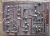
could someone please take alook at the attached pics and tell me whats wrong with the PCB i have designed. Its driving me mad, as I cant work out why the circuit does not work.:mad:

i would be extremely grateful if someone could work this one out:confused:.

thanks.
 

Attachments

  • CROCCLIPS.jpg
    CROCCLIPS.jpg
    17.6 KB · Views: 1,413
  • REALPCB.jpg
    REALPCB.jpg
    35.1 KB · Views: 1,564
I'm not really qualified to advise, so take me with a grain of salt, but it looks like your control voltage pin isn't hooked up to anything. I think you want it grounded with a 0.01:mu: cap. Hopfully one of the pros can verify this.
 
Hi,

I only glanced at the PCB design, but it looks fine. I haven't seen the PCB itself, so I couldn't tell you if thats ok :eek: 
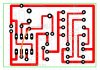
You should go over every connection with a continuoity tester on your PCB, to check that everything thats meant to be connected, is connected.

And when you 'flipped' the design...what was this for? Press'n'peel tranfers method? photoetching? I guess it doesn't really matter if its mirrored horizontally or vertically, but make sure its mirrored! I assumed that what you meant when you said 'flipped' and that would be for the transfer etching method.

it might be easier if you posted a picture of your actual PCB, but I make no promises, debugging can be an arse sometimes.

Blueteeth
 
Question: Are we looking at your attachment from the component side of the board or the trace side. Judging by the lettering I'm assuming component side.
 
Well, now I am curious about pin 5. No one has corrected me yet, but last summer I made this circuit on solderless breadboard, and was pulling my hair out because it did the same thing, led was steady on. I tried all kinds of stuff before I connected pin 5 to gnd. and once I did, if worked fine..... I don't think I had a cap in there either, just a wire. :confused:
 
I think you have the transistor in wrong. What kind is it? Check the pinout. If the base is in the hole that goes to the LEDs, the LEDs will be on all the time.
 
Last edited:
Yeah, I have to agree with andy1845c on this. PIN 5 is not connected to anything. I would certainly try connecting it to ground through a 0.1uF cap. On all the 555 flasher circuit's i've seen, pin 5 is grounded through a small cap.
 
Hi, all thanks very much for the input.:)
When i design in RealPCB the components and tracks are on the same side. this is why i needed to mirror horizontally, to get pins of the 555 in the right place when i put it on the back of the board (where there are no tracks).

I have made the circuit successfully many times on a breadboard, but i have never used the cap connected to ground from pin 5.

I will give this a go though.

I used the photo resist method to produce this board, but i didnt develop it for long enough, so little lines of copper were left connecting tracks, which i scratched off with a stanley. I then cont. checked tracks before i started soldering, everything appeared to be in order.

I have left component leads long, so that i can easily remove them if this doesnt work, however i ensured that they were not shorting anything when i connected the power.

I have included pics of component side, and of track side. I apologise for the shite quality of my photos, my camera sucks, and ive compressed them heavily for users with slow connections;).


thanks very much once again, I just cant express enough how much this is doing my head in.:(
 

Attachments

  • COMPONENTS.jpg
    COMPONENTS.jpg
    68.3 KB · Views: 629
  • TRACKS.jpg
    TRACKS.jpg
    116.1 KB · Views: 499
Last edited:
hi bitem2k,

Checked pcb and circuit, as already stated you have a 0.01uF on pin 5, otherwise looks OK. Can't check the orientation of the transistor.

Whats the transistor type you are using ?. Depending upon the LED types it could be switching 100mA.

What LED's are using, there could be a more efficient way to connect them.

One point I would recommend when using a variable resistor as you are,
always link one end on the pot to the slider. As you know some pots can be a little noisy.

When one end of the pot is linked to the wiper, the maximum resistance in circuit never exceeds the value of the pot.

EricG
 
Last edited:
Hi thanks very much eric.

ericgibbs said:
Whats the transistor type you are using ?. Depending upon the LED types it could be switching 100mA.
What LED's are using, there could be a more efficient way to connect them.

BC337 NPN transistor. I calculated the resistor value needed to saturate the base, based on running the SuperBright leds at around 3.8v @ 20mA.

4*20mA = 80mA and the bc337 can handle 800mA.

I think i need 8mA of current to saturate the base, and have calculated resistor value allowing for the transistor base voltage drop.

Im running on a 6v battery consisting of 4 * AA cells.
I want to run the leds at max voltage, which is 3.8v so i cant link two in series. Is there a more efficient way that you know of?

ericgibbs said:
One point I would recommend when using a variable resistor as you are,
always link one end on the pot to the slider. As you know some pots can be a little noisy.

When one end of the pot is linked to the wiper, the maximum resistance in circuit never exceeds the value of the pot.

Im sorry but i dont know quite what you mean about the pot.
I know it has three pins, but im only using two. Are you suggesting that i should link 1 pin to + side of circuit, and other two together and connected to neg side?

How does noise effect this circuit and could this be the reason it doesnt work?

I have checked the cont. of all components and track, but i just cant find why it wont work. Ive gone completely over the pcb layout many times but
i just cant understand why it doesnt work.:confused:

Is there any tips you could give me for debugging with a multimeter?:D

thanks very much.:)
 
bitem2k said:
Is there any tips you could give me for debugging with a multimeter?

By conecting your meter ( set to DC range ) between ground and pin 3 of the 555 you can see if you are getting pulses from it.
 
hi bitem2k,

The reason I asked about the LED type, because your orginal circuit shows a +9v supply.

I'll do a sketch of the pot wiring I suggested, will post it later.

Since you got the 555 very hot, are you using the same 555 ?.
It could have died!.

While the unit is switched ON, ground the base of the transistor to 0V, the
LED's should go OFF.

Lift one end of the transistor base resistor out of the pcb, if the LED's
stay ON, the transistor could be faulty.

While the resistor end is out, measure the voltage on the 555 output pin.
Turn the pot to give the slowest pulse rate, the DVM should read about half
the supply voltage if the 555 is pulsing.

Let's know what you find.

EricG

edit:
Is the pcb track view you have posted the component side and we looking at the copper track thru the pcb???
 
Last edited:
I changed the supply to 6v.
I have tried two 555's. They both still work in the breadboard circuit.
I will try other things you said in a while.
The pcb track view, is the view of the copper side, but the components are displayed on the copper side in the program also (this is why it needs to be flipped).

thanks.
 
hi,
Have downloaded your pcb artwork, if I use my Paint Shop Pro to 'flip' it or 'mirror it' it makes the layout incorrect.

So it suggests to me, that I am looking at the track thru the pcb on your original layout.

Can I suggest you try the same in your PSP or equivalent.

Eric
 
Okay. Your transistor is wrong, but I had to wait for confirmation as to which side we were looking at. Just to prove it to yourself, look at your layout on the computer screen. Now, imagine an NPN transistor (TO92) between the thumb and forefinger of your right hand, with the flat face against your finger. The emitter will be on the bottom. Try to plug it. Yep, you have collector where emitter should be.
 
Well, first of all, it seems to me like the assembled board confirms that the artwork is OK. Am I missing something?
AllVol said:
Okay. Your transistor is wrong, but I had to wait for confirmation as to which side we were looking at. Just to prove it to yourself, look at your layout on the computer screen. Now, imagine an NPN transistor (TO92) between the thumb and forefinger of your right hand, with the flat face against your finger. The emitter will be on the bottom. Try to plug it. Yep, you have collector where emitter should be.
Did you look at the datasheet of the BC337? Collector and emitter are swapped relative to the "norm", like a 2N3904.
 
No, I did not. If its not one thing, it's a mother. Silly me, I just thought everyone used normal transistors.
 
AllVol said:
No, I did not. If its not one thing, it's a mother. Silly me, I just thought everyone used normal transistors.
Silly, ain't it? I can understand strange pinouts in RF transistors like MPSH10, where base and emitter positions are swapped to minimize C-B capacitance, but what is BC337's excuse?:confused::D
 
ericgibbs said:
hi,
Have downloaded your pcb artwork, if I use my Paint Shop Pro to 'flip' it or 'mirror it' it makes the layout incorrect.

So it suggests to me, that I am looking at the track thru the pcb on your original layout.

Can I suggest you try the same in your PSP or equivalent.

Eric
I used photoshop to flip horz. The tracks connect up to the pins of the 555 correctly. When i didnt flip, the tracks connected to the 555 incorrectly and just made it very hot.

The bank of leds all turn on, the transistor passed all the tests that you previously stated, so it must be a problem with the 555 bit.

I have included a schematic for the bc337, showing the pins.

I think im just going to ditch this pcb now. Im utterly sick of it.

Can someone please pm me an address that i can send this to, so someone can check it and tell me what im doing wrong.
Its probably something really stupid that im doing but ive just hit a brick wall.

The frustrating world of electronics:mad:!

Thanks very much:):)
 

Attachments

  • NEW.jpg
    NEW.jpg
    17.6 KB · Views: 601
  • BC337.jpg
    BC337.jpg
    3.9 KB · Views: 513
  • TRACKS.jpg
    TRACKS.jpg
    28.2 KB · Views: 810
Last edited:
Status
Not open for further replies.

Latest threads

New Articles From Microcontroller Tips

Back
Top