You smelled something burning?
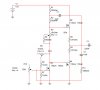
The little 2N4401 and 2N4403 have an absolute max allowed heat dissipation of only 625mW. In a 9W amplifier each one must dissipate 3W at full output. They will fry.
The simulation software doesn't know that.
The little transistors have a max allowed current of only 600mA. At 9W into an 8 ohm speaker the peak current is 1.5A. Bridged it will be 3A. They will fry.
The sim software also doesn't know that.
You need to use power transistors like the TIP31 and TIP32 mounted on a heatsink. But their current gain is much lower than little transistors so the circuit needs additional transistors added.
Use Sziklai pairs (look in Google) for high linear current gain.
The "bias servo" transistor needs to be mounted on the same heatsink as the output transistors so it can compensate their current for changes in their temperature.