Continue to Site

Welcome to our site!

Electro Tech is an online community (with over 170,000 members) who enjoy talking about and building electronic circuits, projects and gadgets. To participate you need to register. Registration is free. Click here to register now.

  • Welcome to our site! Electro Tech is an online community (with over 170,000 members) who enjoy talking about and building electronic circuits, projects and gadgets. To participate you need to register. Registration is free. Click here to register now.

Signal Splitter

Status
Not open for further replies.
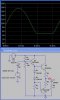
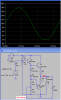
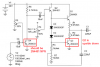
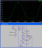
I simulated your amplifier circuit. The input has a transistor that pulls up the voltage very well. But it has only a resistor to pull the voltage down. As the voltage gets lower then the current in the resistor becomes too low to work properly. Then the bottom of the output waveform clips.

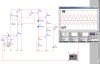
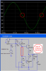
You need to replace the pull-down resistor with a constant current sink or "a boostrapped" pair of resistors.

Your amplifier doesn't have a voltage gain, it has a small loss.
 

Attachments

  • 3 transistor amp.JPG
    3 transistor amp.JPG
    43.3 KB · Views: 157
Hi Nigel,
My sim had the wrong transistors and wrong resistor values but it showed that the pull-down resistor can't properly drive the PNP transistor. I added bootstrapping and changed the bias voltage a little and even though there is no negative feedback, the output now looks pretty good.
 

Attachments

  • bootstrap.PNG
    bootstrap.PNG
    21.4 KB · Views: 136
The bootstrapped curcuit looks good and I might try it.

Also how would you make them run is class_AB mode?

The curcuits are shown without the first stage, wich you could help me with.

And lastly, what about the MOSFET curcuit.
 
catcat said:
The bootstrapped curcuit looks good and I might try it.

Also how would you make them run is class_AB mode?

How do you make it class A? - the same applies.

The curcuits are shown without the first stage, wich you could help me with.

There are plenty of existing circuits about already.

And lastly, what about the MOSFET curcuit.

Waste of time, you don't have enough voltage - and why only 20V?.
 
I saw a MOSFET hi-fi amplifier project that said it would run with a 5V supply.

Anyway, I simulated the bootstraped curcuit with a PNP one-transistor input stage, but it did not help with gain.
 

Attachments

  • inshot.jpg
    inshot.jpg
    135.7 KB · Views: 130
His woofer is a tiny 5.25 inch one that might blow up if it receives more than 18W (18 Watts), even though it might be marked "100w" (100 whats).

The diodes in the circuit bias the output transistors in class-AB so their average current is low. If the diodes are replaced with a resistor then the output transistors would operate in class-A and would get very hot due to the high current all the time. If the diodes are shorted then the output transistors operate in class-B with crossover distortion.

I wonder if a lousy old LM324 opamp would show its crossover distortion in a simulation? Even with plenty of negative feedback its very low bandwidth would have a terrible time trying to eliminate its crossover distortion.
 

Attachments

  • class-B.PNG
    class-B.PNG
    23.1 KB · Views: 140
catcat said:
I saw a MOSFET hi-fi amplifier project that said it would run with a 5V supply.

Yes, no problem with that - but it all depends how much power you want from your amplifier - I suggested with a well designed transistor amp you may be able to get 10W (20W bridged) from your 20V supply - which you still haven't explained?. With a MOSFET amp you won't get anywhere near that.

Anyway, I simulated the bootstraped curcuit with a PNP one-transistor input stage, but it did not help with gain.

That's because it's nothing like an audio power amplifier - for a start (as Audioguru also said) the driver needs to be PNP - but you still have a LOT of circuitry missing and incorrect.
 
The woofer is an 8ohm 5.25"" with a rating of 70W rms, and form my listening tests, is has as much bass as a standard 8 inch woofer.

I actually do not really need more than 15 watts, with my current designs I can get about 0.5w of peak power and thats almost enough for listening moderatly loud in the same room. The reasons for more are for listening in other rooms and always having a little more just in case.
 
Your PNP input transistor is backwards. It should be an NPN. Its biasing is bad because when it warms it draws more current and will saturate. When it cools it draws less current and will be cutoff. You will need to adjust the trimmer pot for each transistor because they are all a little different.

The PNP output transistor is upside down.

Without any negative feedback the distortion will be horrible, about 40%.

It is too bad you saved your schematic as a fuzzy JPEG file type. I made it more compact.
 

Attachments

  • inshot.PNG
    inshot.PNG
    42.4 KB · Views: 143
Here is the amp with Q2 as a PNP with DC negative feedback so its biasing stays correct. It is pretty sensitive since now, it is nearly at full output with an input of only 46mV RMS. Its distortion is horrible, about 40%.
 

Attachments

  • amp with gain.PNG
    amp with gain.PNG
    26.2 KB · Views: 137
audioguru said:
Here is the amp with Q2 as a PNP with DC negative feedback so its biasing stays correct. It is pretty sensitive since now, it is nearly at full output with an input of only 46mV RMS. Its distortion is horrible, about 40%.

Getting better though! :p

One more transistor (NPN) and it's finally going to be an amplifier! - although personally I'd add at least another one, replacing the horrible two diodes with a Vbe multiplier!
 
I can get the transistor ones to work, the mosfet versions didnt on the simulator.

I cannot make a good simulated input stage, phase splitter, or voltage amplifier.
 
catcat said:
I can get the transistor ones to work, the mosfet versions didnt on the simulator.

I cannot make a good simulated input stage, phase splitter, or voltage amplifier.

If you insist on playing with simulators, why not get an existing amplifier and simulate that? - from what you've posted so far you don't have the faintest clue how to design an amp? :(
 
On my circuit with the PNP input transistor, I just noticed that its input impedance is extremly low. It needs an amplifier to drive it.

EDIT: I smell something burning. It is the little output transistors that are burning.
 
I think Ron H. has a new hat with burning tail feathers on it.
 
I just did not know what transistors to put.

When I tried the transistor bias servo instead of two diodes I smelled something burning.
 
Last edited:
catcat said:
I just did not know what transistors to put.

When I tried the transistor bias servo instead of two diodes I smelled something burning.

Assuming you mean a Vbe multiplier?, you need to have it adjusted so the transistor is fully ON, then slowly turn it up for the bias you want.
 
Status
Not open for further replies.

Latest threads

New Articles From Microcontroller Tips

Back
Top