Continue to Site

Welcome to our site!

Electro Tech is an online community (with over 170,000 members) who enjoy talking about and building electronic circuits, projects and gadgets. To participate you need to register. Registration is free. Click here to register now.

  • Welcome to our site! Electro Tech is an online community (with over 170,000 members) who enjoy talking about and building electronic circuits, projects and gadgets. To participate you need to register. Registration is free. Click here to register now.

Signal Mixer/Summing circuit

Status
Not open for further replies.
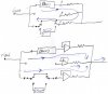
I was wondering if any of you could confirm that this would work as a summing circuit/signal mixer?

The second OpAmp I believe is used to phase invert again after the first one and the first I'm assuming is a buffer.

**broken link removed**

Any help is appreciated. :)
 
That circuit will indeed sum (and linear mix as the term is used in audio control consoles, not non-linear mix as an RF mixer would) the input signals.

The first op amp is an inverting summer with a gain of one which provides a virtual ground to all the input resistors, which insures there is no interaction or crosstalk between inputs.

The second op amp is just an inverter (with gain equal to R23/R22) if you want no phase inversion from summing input to output.

Awesome thanks a lot. :D I saw it at school and was scared I forgot the values. Thanks. :D
 
The first opamp is just a summer it does not create a virtual ground anything and doesn't insure seperation of crosstalk between the devices.
If one of them were to be put in bypass mode you would be literaly shorting the input to the output and it could set the whole mess of units into oscillation.

To solve this you must use a opamp buffer on each individual input between the input (output of the device) and the summing resistor.
For a minimum parts count a unity gain buffer is just fine but you should also use a capacitor on the output of each opamp (before the summing resistor) stage as to block dc output offset as this will get amplified in each successive stage as well.

jer :)
 
The first opamp is just a summer it does not create a virtual ground anything and doesn't insure seperation of crosstalk between the devices.
If one of them were to be put in bypass mode you would be literaly shorting the input to the output and it could set the whole mess of units into oscillation.

To solve this you must use a opamp buffer on each individual input between the input (output of the device) and the summing resistor.
For a minimum parts count a unity gain buffer is just fine but you should also use a capacitor on the output of each opamp (before the summing resistor) stage as to block dc output offset as this will get amplified in each successive stage as well.

Sorry, but you are completely incorrect - the circuit is a perfectly standard virtual earth mixer, and doesn't require any buffers on the inputs.

The resistor values are a bit strange though (who uses 11K?), and really should be higher to give a more acceptable input impedance (use 47K or 100K), plus coupling capacitors DC blocking the inputs.
 
I guess that you don't understand the point that I was making?

I have been building mixer circuits for years and in order to have complete seperation of crosstalk between each input channel there must be a buffer in order to keep the signal for getting back to the input.

It can be on the send or receive side.
The original layout shows none.

The way it is shown I am assuming that this is to be used with effect devices or stompbox's of some sort although this was not made clear in the beginning.

If it is to be used with a typical stompbox then when it is put into bypass it can/will then short the output to the input of all the devices cause a feedback loop and if one of the devices has enough gain then the system WILL oscillate freely.

I know this to be true, Because, I have done this on some of my very first mixer projects.
Since then I have always used buffers on all sends and receives in mixer circuits.

I did not say that it wouldn't work at all, Just that there is a possibilty of feeback problems the way it has been shown.


jer :)
 
Last edited:
I agree with Nigel. The circuit shown has a virtual ground which will eliminate crosstalk or feedback between inputs.

You may have been building mixer circuits for years but that doesn't mean you've been doing it right. Why in heck would you "put into bypass" by shorting the circuit output to the input? That's really bad design. No wonder you had problems with oscillations.:rolleyes:
 
The only thing that doesn't make sense is the fact that "signal" is attached to all inputs. I assume this is a "typo".
Also, when SPDT2 is in the UP position, the output will be attenuated by the ratio R24/(R22+R24).
 
Okay Whatever!
Explain to me where the virtual ground is,
And, NO, have have never had any issues with my mixer circuits when they are properly designed.
And your typical stompbox shorts the input to the output ,some may not, but you can check this with a VOM or continuity checker if you don't believe me.
Those that do not,Already have unity gain buffer built in to them and it won't be any issue.

If you want to argue about simple logic I am not here to do that.

On page 247 of this book in fig. 6.52a shows the proper configuration that should be used for a Send and Return circuit.

https://www.electro-tech-online.com...state_guitar_amplifiers_teemu_kyttala_v10.pdf

A virtual ground is where the ground as at 1/2 Vsupply so that the opamps can run off of a single end supply and all of the inputs and output signal grounds must be connected to this ground inorder for the circuit to work properly.

jer :)
 
Last edited:
Also in the schematic the output (assuming C6) is tied to your what should be the ground or even virtual ground (which ever power supply configuration you choose to use) rendering you absolutely no output at all !

jer :)
 
I guess that you don't understand the point that I was making?

Yes, I understood what you were saying, but it was completely 100% incorrect - the design above (while it has a number of problems) is a true virual earth mixer.

I have been building mixer circuits for years and in order to have complete seperation of crosstalk between each input channel there must be a buffer in order to keep the signal for getting back to the input.

In which case you've been building them wrong all these years, I've also built many mixers over the years, including a decent size one back in the 70's I used to do the full PA for a local band I engineered for.

It can be on the send or receive side.
The original layout shows none.

The way it is shown I am assuming that this is to be used with effect devices or stompbox's of some sort although this was not made clear in the beginning.

If it is to be used with a typical stompbox then when it is put into bypass it can/will then short the output to the input of all the devices cause a feedback loop and if one of the devices has enough gain then the system WILL oscillate freely.

You seem totally confused about how stopboxes and bypass switches work?, and neither have anything to do with the mixer circuit.

I know this to be true, Because, I have done this on some of my very first mixer projects.
Since then I have always used buffers on all sends and receives in mixer circuits.

I did not say that it wouldn't work at all, Just that there is a possibilty of feeback problems the way it has been shown.

You are mistaken, and have been doing it wrong all these years - also buffers wouldn't prevent feedback in any way - they might even make it more likely, if anyone was (rather stupidly) linking the output back to the input.
 
Also in the schematic the output (assuming C6) is tied to your what should be the ground or even virtual ground (which ever power supply configuration you choose to use) rendering you absolutely no output at all !

That's an obvious drawing error on the circuit :D

The invert/non-invert switch is also wired completely wrongly, the common should go to the output of the circuit, and the two switched connections to the outputs of either opamp.
 
Explain to me where the virtual ground is,
Virtual ground has two meanings. One is the definition you provided:
A virtual ground is where the ground as at 1/2 Vsupply so that the opamps can run off of a single end supply and all of the inputs and output signal grounds must be connected to this ground inorder for the circuit to work properly.
The virtual ground being discussed here is at the inverting input of OA3. This type of virtual ground is a point in the circuit that is maintained at some known reference, such as ground, without actually being connected to it. This is commonly the junction of the resistor divider between an op amp's input and output at the negative input pin, while the positive input pin is grounded (usually through a resistor). The op-amp maintains this virtual ground by making the output be whatever it takes to rebalance the input divider.

Since this node in the OP's circuit is at zero volts, no crosstalk can occur between inputs.

 
Last edited:
I have never heard it called a virtual ground.
I have always know it to be called the summing piont were all of the voltages are summed (added ) together.

If I have been doing it wrong all of these years then how come the little mixer I have made works perfectly as you have yet to explain where I was 100% incorrect.

I have built all of my own equipment through the years and they have worked flawlessly until I could afford to by a commercial mixing board (mackie 32-8) in which my DIY version still rivals it today (30 years later) as far sound quality goes.

So apparently your terminology may different than mine so there is know reason to insult my intelligence or abilities as a circuit designer.

In the schematic it states pedal so I am assuming Stompboxes.

If you recall (from the 70's) that usaly DPDT (sometimes just a SPDT but improper) switch , Switches the effect in an out of the circuit and when it is switched out the input is directly connected to the output.

Since all of the inputs are tied together should one the Pedals be a delay unit for a slapback type of echo(For an example) it will continue to echo instead of being a single slap back and evenualy start to oscillate profusely if its gain is set high enough.

I am not trying to start any flaming war here I don't know how to explain it any simpler than that.

If you don't understand the bypass switch arrangement then I can put up an example if needed, But I am sure that you do understand its configuration and should not be necessary.

jer :)
 
Maybe this will help you to understand what I am trying to explain.

jer :)
 

Attachments

  • mixer.jpg
    mixer.jpg
    63.1 KB · Views: 283
i believe the usage of the term "virtual ground" to describe the inverting input of an op amp with negative feedback, while the noninverting input is grounded, predates the other usage of the term by several decades. I learned about it in the early 1960's, when op amps were made of discrete components (the first IC op amp, the uA702, was invented in 1964), and I don't remember seeing any applications that used a bias voltage to create the other type of virtual ground (to allow single supply operation) until many years later.

In your mixers, do you sum to an inverting input, or a noninverting input?
 
In most of my circuits I prefer to use the inverting input configuration,But it depends on what the circuit is for.
The gain calculations for the inverting is more straight foward as well.
Where gain=Rfeedback/Rinput ,vs, gain= 1+(Rfeedback/Rinput) for the non inverting configuration.
In most cases it can also eliminate the need for a resistor from the +input to ground thus reducing parts count.

The only time I use the non-inverting configuration is when it is imperative that the signal polarity must not be changed or if I need a high impedance input for a high gain buffer for things such as a guitar or high impedance microphone or using the unity gain buffer configuration.
When driving a Balanced output the signal polarity becomes irrelevant as reversing two wires corrects the situation if needed.


jer :)
 
Last edited:
Status
Not open for further replies.

Latest threads

Back
Top