It might be a bit much for a first project.
I suggest building the triangle generator first, then adding the sinewave on, and later you can add an attenuator and a buffer.
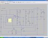
I took the sinewave generator circuit from the site linked below. It shows you how to calculate the values of the components to get different frequencies, of course you need to make sure the op-amp is good enough to handle the maximum frequency you want to generate.
You could use a rotary switch to change the value of C1, so you could have say 2Hz to 20Hz, 20Hz to 200Hz, 2kHz to 20kHz and 20kHz to 200kHz, you'll need a reasonably fast good op-amp to go above 20kHz.
Then there's the choice between the first and second sine wave circuits. The first may seem simpler but it requires a dual ganged pot and rotary switch so I recommend the second circuit because it only needs an extra single pot and it can easily be added to an existing triangle wave generator.
I'll give you more information, if I haven't put you off.
")
[/QUOTE
could you give me more info on it so i can get a picture of whats going on maybe its a bit much as you say and build the triangle one first