Electro Tech is an online community (with over 170,000 members) who enjoy talking about and building electronic circuits, projects and gadgets. To participate you need to register. Registration is free. Click here to register now.
Welcome to our site! Electro Tech is an online community (with over 170,000 members) who enjoy talking about and building electronic circuits, projects and gadgets. To participate you need to register. Registration is free. Click here to register now.
hi was just wondering has any one any information on signal generators what are they used for and are they must while having oscilloscope any information on the sight about them
Signal generators come in many shapes sizes and functions.
I have three devices on my bench which could be regarded as signal generators.
A Hewlett Packard HP8640B. An RF signal generator, 500khz to 512Mhz, very stable frequency, AM and FM modulation, an accurate attenuator output voltage 3v to 0.1µv.
Used for testing various radio equipment.
A Hewlett Packard 3312A. A function generator, 0.1hz to 10Mhz, sine, square and triangle waveforms. The output waveforms may be offset with DC. Output voltage 0.01 to 10v, a very basic uncalibrated attenuator. A second oscillator may be used to Am or FM modulate the main oscillator with sine square or triangles.
A totally over the top piece of equipment for my needs but it fits in the available space.
Used for low frequency (less than 1Mhz) testing of various odds and sods.
A home made DDS* oscillator, 0 to 50Mhz, fixed 1 volt output.
Very stable with fine control of the frequency, 1 hz resolution throughout its range.
Used as a general purpose signal source, the fine frequency resolution is usefull when checking the series and parallel resonant frequencies of quartz crystals.
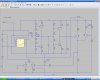
Here's a couple of schematic idea for a signal generator, I designed while ago. I've never built these circuits but they both should work.
Both use the same triangle wave generator but the method for generating the sine wave is different, the first one uses a low pass filter and the second a non-linear shaper. I'll post more, if you're interested.
Note, they're not quite finished, rotary switches need to be added to change the the capacitors to get different frequency ranges, the type of op-amp needs selecting and it would also be good idea to add a buffer amplfier.
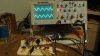
Some might remember this one I've discussed here. I got around to building and testing it some time ago. It works great, up to about 500KHZ. ( I hope to get 1MHZ when it transfer it to a better board. ) I was a little concerned about the level shifting network for the final sine wave shaper, but it has been very stable. It might look complicated with all those transistors, but it's really very simple. The reason I wanted to use transistors was because of thier ability to take a lickin' and keep on tickin', and because I wanted to breadboard the design and not deal with opamp's weird breadboard behavior.
The weakness is the frequency isn't really adjustable. I change it by changing the timing cap.
Yeah, I hadn't built it when we were discussing it. I have a few op-amp sig-gens I've built too. But I just wanted to use BJT's for this one. Also thinking about replacing the timer chip sometime in the future.
thanks for all the replys and i see exactly now what there for what would be a common one on the work bench even tho im in the early stages of electronics i still want to kit out my bench as i go along
Here's a couple of schematic idea for a signal generator, I designed while ago. I've never built these circuits but they both should work.
Both use the same triangle wave generator but the method for generating the sine wave is different, the first one uses a low pass filter and the second a non-linear shaper. I'll post more, if you're interested.
Note, they're not quite finished, rotary switches need to be added to change the the capacitors to get different frequency ranges, the type of op-amp needs selecting and it would also be good idea to add a buffer amplfier.
hi hero just looked at the schematics
do you think it would be a bit much as a first project looking at the schematics i think i can handle it could you post more thanks
I suggest building the triangle generator first, then adding the sinewave on, and later you can add an attenuator and a buffer.
I took the sinewave generator circuit from the site linked below. It shows you how to calculate the values of the components to get different frequencies, of course you need to make sure the op-amp is good enough to handle the maximum frequency you want to generate.
You could use a rotary switch to change the value of C1, so you could have say 2Hz to 20Hz, 20Hz to 200Hz, 2kHz to 20kHz and 20kHz to 200kHz, you'll need a reasonably fast good op-amp to go above 20kHz.
Then there's the choice between the first and second sine wave circuits. The first may seem simpler but it requires a dual ganged pot and rotary switch so I recommend the second circuit because it only needs an extra single pot and it can easily be added to an existing triangle wave generator.
I'll give you more information, if I haven't put you off.
I suggest building the triangle generator first, then adding the sinewave on, and later you can add an attenuator and a buffer.
I took the sinewave generator circuit from the site linked below. It shows you how to calculate the values of the components to get different frequencies, of course you need to make sure the op-amp is good enough to handle the maximum frequency you want to generate.
You could use a rotary switch to change the value of C1, so you could have say 2Hz to 20Hz, 20Hz to 200Hz, 2kHz to 20kHz and 20kHz to 200kHz, you'll need a reasonably fast good op-amp to go above 20kHz.
Then there's the choice between the first and second sine wave circuits. The first may seem simpler but it requires a dual ganged pot and rotary switch so I recommend the second circuit because it only needs an extra single pot and it can easily be added to an existing triangle wave generator.
I'll give you more information, if I haven't put you off. [/QUOTE
could you give me more info on it so i can get a picture of whats going on maybe its a bit much as you say and build the triangle one first
If you just want to build a triange wave generator, everything to the right of R4 (including R4) can be ignored.
Then when you've got it working you can build the rest of the circuit.
Once you've got the whole thing working, you might want to add an output buffer and an attenuator, an audio amplifier IC can be used for that but we'll cross that bridge when we come to it.
I suppose you want me to recommend a suitable op-amp too, it's getting late now, I'll look tomorrow.
The original poster seemed to be happy to accept help with building a signal generator.
Anyway to answer the question, signal generators are used to test circuits such as amplifiers. A 2Hz to 200kHz signal generator is pretty much limited to audio an a little bit more. The good thing is at higher frequencies than 200kHz you normally only need square (for testing digital circuits) and sine (for RF circuits), so it becomes simpler to design in some reapects but more complex in others. I'll explain why if anyone's interested.
I forgot to say that to test a signal generator you really need a 'scope, luckily a PC's sound card can be used as a poor man's 'scope in the frequency range of 20Hz to 20kHz, with the addition of some software so you don't need to own a 'scope to test my design. The trouble is, the usable range for the square and triangle wave shapes will be <20kHz, probably about 2kHz and 200Hz respectively. At higher frequencies the triangle waves will look more sinusoidal and the square waves will look more triangular, but as long as you're aware of this, it doesn't matter.
I've just realised that a very fast op-amp is required if a +/-15V PSU is used the peak to peak voltage will be near 30V which means to get a rise and fall time of 0.5µs, the slew rate will need to be 60V/µs
I think reducing the voltage to +/-6V is a better idea, that way the slew rate can be more than halved.
Reducing the maximum frequency to 100kHz would also make it much more feasible.
This site uses cookies to help personalise content, tailor your experience and to keep you logged in if you register.
By continuing to use this site, you are consenting to our use of cookies.