Continue to Site

Welcome to our site!

Electro Tech is an online community (with over 170,000 members) who enjoy talking about and building electronic circuits, projects and gadgets. To participate you need to register. Registration is free. Click here to register now.

  • Welcome to our site! Electro Tech is an online community (with over 170,000 members) who enjoy talking about and building electronic circuits, projects and gadgets. To participate you need to register. Registration is free. Click here to register now.

signal clipping

Status
Not open for further replies.

chinsoon

New Member
hi there,

i was given a task:

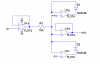
i am supposed to build a circuit that clips a signal source (signal generator) output to a voltage range of +/- 1V. this voltage range will then be used as input to a sound card. thats why i need to make sure that the input voltage to the sound card must not exceed 1V peak.

i was thinking of using diodes where i used to see it on other circuits, connecting the output to the rail or something. but i could not get the precise design out.

any idea how can i do that? or any BETTER idea on how to clip the signal at 1V

thanks
 
One method is using a special version of a opamp voltage follover, where you put in a diode like pic below:

**broken link removed**

However, this only limits the maximum positive voltage. You need to design a "reverse" circuit where the diodes shifts directions and you'll us -1 volt on the Vlimit input.
 
yup.. its to protect the sound card.

i have seen some circuits that look like this:
Opamp Voltage Limiting

this example was given as a internal block of an op amp.. i wonder is it a usable circuit, or its just simulation of concept. but somehow i have seen that diode configuration in some NAND gates... 74SL family i guess...

any idea how it is done to clip a voltage of +/- 1V?
 
diode clipping will create bad distortion. Would the nominal signal be under the threshold of the diodes.
 
This will clip at ±1V. It will also severely distort the signal if the input signal swings past ±1V. If you don't need high input impedance and low output impedance, you can omit U1a and U1d, and use a dual (TL072) op amp. The +1 and -1V references can be high resistance voltage dividers.
The supply voltages can be as high as 15V each, and they don't have to be equal in magnitude.
 

Attachments

  • symmetrical clipper.PNG
    symmetrical clipper.PNG
    12 KB · Views: 230
Somebody might like the severe distortion as FUZZ for their geetar.
 
hmm...

i just remembered that i have seen the op amp circuits before...

but this circuit will just work fine right?

if i connect any circuits to the soundcard, should i take care of the current that will be flowing into the soundcard? -- even if i have limited the soundcard input to +/-1V?

____________________________________________________________________________

anyway.. we're next asked to design another buffer/driver circuit that will be used as a driver to drive a load based on the output of the sound card...

my question is:

as i know, the output from the sound card has a very small current and voltage... so correct me if i am wrong, i need to design an amplifier (probably an op amp) to amplify the voltage, followed by a current buffer (probably a common base BJT configuration) to drive the load?

i just need to get a rough idea because its a design course, so the exact load and requirements of the design will only be disclosed when i attend the lab session.

thanks for all the help guys
 

Attachments

  • diode_clipper_2.gif
    diode_clipper_2.gif
    3.8 KB · Views: 221
Last edited:
An audio amplifier is used to drive a low impedance speaker.
You can make your own audio amplifier with an opamp driving some transistors, or use an audio amplifier IC.

Usually an audio amplifier has complementary emitter-followers at the output for equal push-pull high currents into a speaker.
 
yeah.. thats what i thought... normally speakers have around 4 ohm impedance...

so i would assume that it silly to connect the sound card output to an op amp since an op amp offers a very high input impedance? i was thinking that i might need to amplify the signal out from the soundcard, then connect a buffer to it

note: the driver circuit might not be used to drive a speaker. so far what we have done was to do data acquisition using the soundcard, and use a computer software to analyze the signal. the next part would be to use a soundcard to drive a load without loading the soundcard.
 
Last edited:
Home speakers are usually 8 ohms. Car speakers are usually 4 ohms but the ones in my car are 2 ohms for high current and high power.
Use an opamp to amplify the output of your sound card if you want.
Use an audio amplifier if you want.
 
The 'mid' drivers I take out of desktop cube speakers for PC's tend to be 4 ohm. But I get 8's as well, it's really across the board.
 
Status
Not open for further replies.

Latest threads

New Articles From Microcontroller Tips

Back
Top