Continue to Site

Welcome to our site!

Electro Tech is an online community (with over 170,000 members) who enjoy talking about and building electronic circuits, projects and gadgets. To participate you need to register. Registration is free. Click here to register now.

  • Welcome to our site! Electro Tech is an online community (with over 170,000 members) who enjoy talking about and building electronic circuits, projects and gadgets. To participate you need to register. Registration is free. Click here to register now.

Short beep (from a hi latch)

Status
Not open for further replies.

ThomsCircuit

Well-Known Member
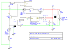
Im sure this has been discussed before and i understand more than i did a year ago. This gadget i made works well but it is quiet. Id like to add a beep each time the button (TTP223 touch pad) is pressed. I have it configured to latch hi when pressed to turn on a 5V fan by transistor then latch low to stop the process.

I know the 555 can do just what i need but it requires a low pulse to properly function. Perhaps there is a way to use what i have and send (create) a low pulse to the 555 using the output of the TTP. I have NAND gates CD4093 and 4013 debouncers. my powersource is 5V and the buzzer is a piezo type.

20211108_174041.jpg
20211028_144548.jpg
 

Attachments

  • poolSpinnerF.png
    poolSpinnerF.png
    14 KB · Views: 216
  • 555 Timer 2.GIF
    555 Timer 2.GIF
    6.3 KB · Views: 231
Hi

replace the switch in your 555 diagram with either a npn bjt or nmos transistor. When the transistor turns on, it will trigger the 555.
 
if not then perhaps two 555 chips. one with an NPN to beep when it is switched on (positive latch) and the other with a PNP to trigger with the negative latch. I would need a sketch for the PNP version. I think it would be configured differently than the NPN
 
555 Timer 2.GIF

--------------------------------------------------------------------------------------------------
CORRECTION PIN1 FROM TTP
Here I would configure two 555 ICs outputting to the same buzzer.
Default on powerup 555#1 is high and 555@2 is low (555#2) sounds buzzer.
When pin1 from the TTP goes high (from button press) the NPN would cause pin2 on 555#1 to go low and 555#2 to go high.
When the button is pressed again 555#1 will go high and 555#2 will go low sounding the same buzzer.

Will that work?
 
Beep Beep.png

replace the switch in your 555 diagram
Could use a bit of knowledge with this.
Wanting to know if this is logically correct and if it can be simplified. Your last reply about the NPN helped me understand the use of transistors. Thank you. Im hoping you can help me again with this. From the article that accompanied the sample beep circuit R11 & C9 control the duration of the buzzer. Can this be simplified by using one pair for the buzzer?
 
will it also work when the button is pressed to turn it off as well? On beep, Off beep

The button in your 555 schematic post#1 doesn't do that.
The 555 doesn't latch either.
The 555 has a "differentiator" circuit at the trigger so when the switch is pressed a short 5v to 0v pulse is sensed at the trigger input causing the monostable 555 timer to run even if the button is held down. The output will go high for about 473 milliseconds, but it won't "latch" high. If you replace the switch with a transistor as suggested, the behavior is the same, except a high input to the transistor will trigger the timer. That is what you wanted in post #1.

If you want something different, please describe the function you want or what you trying to accomplish.
 
Last edited:
If you want something different, please describe the function you want or what you trying to accomplish.
A short Beep each time the button is pressed. Meaning each time Pin3 on the TTP is triggered.
The latching i was referring to was not the 555 but the TTP instead. The TTP is currently configured to latch (pin1) when pin3 is triggered.
except a high input to the transistor will trigger the timer.
Just so i understand how the NPN works. When The base of the NPN receives a positive or goes from low to high it allows the flow of current to flow from the collector to the emitter thus causing pin 3 on the 555 to go from high to low. I am still trying to understand how "edges" work so please bare with me.
Now i do not want to re-design the TTP / FAN circuit so if i need to use 2 555 ICs it fine. I thought that what i presented in post #7 would work. bummer.
 
Hi

You can try this.
The circuit is basically a dual edge detector made with a CD4093B chip.
Each time the output of the TTP223 changes state, a short "high to low" pulse will be generated to trigger a single 555 monostable timer.
R2/C1 and R5/C2 set the trigger pulse width. The values shown should work but the pulse doesn't need to be very long. If they need adjustment, use the same values for each R/C pair. The 555 output pulse width will control the length of the "beep". I'm not sure if you'll need diode D3.

1636560928632.png
 
A dual edge detector made with a CD4093B chip.
Thank you E.
I want to understand this so I've some questions. Well just one anyway. How does this work?
Mostly how does the 4093's configuration function.
 
Last edited:
You can try this.
Sorry but i have an issue getting it to work properly.

It doesnt beep with any button press (on or off)
I added the cap between 7 & 14 on the CB4093 and also added one between pin 1 & 8 on the 555
I jumped the 1 unused input on the 4093 and connected them to VCC
First I made sure there was current to both ICs then checked their wiring.
The 555 circuit has what the author calls a conditioner consisting of a cap between R3 & R4
I do not have a oscillator so i cannot see the pulse BUT if i bypass the conditioner the circuit functions but only on the (off press) so the 4093 does work and since the 555 outputs high on pin 3 after a press (off only) that IC functions too. I increased the value of R on the 555 to 300k to allow a longer beep so i can observe it better.

im providing good images of my BB setup. please let me know what steps i can take to correct this.
 

Attachments

  • 20211111_104003.jpg
    20211111_104003.jpg
    929.5 KB · Views: 203
  • 20211111_111436.jpg
    20211111_111436.jpg
    1.3 MB · Views: 200
  • 20211111_111222.jpg
    20211111_111222.jpg
    1.5 MB · Views: 201
Last edited:
Sorry but i have an issue getting it to work properly.

It doesnt beep with any button press (on or off)
I added the cap between 7 & 14 on the CB4093 and also added one between pin 1 & 8 on the 555 between.
I jumped the 1 unused input on the 4093 and connected them to VCC
First I made sure there was current to both ICs then checked their wiring.
The 555 circuit has what the author calls a conditioner consisting of a cap between R3 & R4
I do not have a oscillator so i cannot see the pulse BUT if i bypass the conditioner the circuit functions but only on the (off press) so the 4093 does work and since the 555 outputs high on pin 3 after a press (off only) that IC functions too. I increased the value of R on the 555 to 300k to allow a longer beep so i can observe it better.

im providing good images of my BB setup. please let me know what steps i can take to correct this.

Use this design instead.
It provides better conditioning of the trigger pulse.
Be sure to connect a 0.1u cap across the power pins of U1 and U2.

R1 can be a 1meg pot if you want adjustable time.

1636649721180.png
 
That worked. The output from the 555 was not enough to produce a sound from my 5V supply. i added a 547. its nice now.
 
That worked. The output from the 555 was not enough to produce a sound from my 5V supply. i added a 547. its nice now.
Hmmm...It should have easily driven the sonalert without an external transistor.
What is the model number for the sonalert?
 

Attachments

  • Screenshot 2021-11-11 at 20-44-45 A-3250 PDF.png
    Screenshot 2021-11-11 at 20-44-45 A-3250 PDF.png
    416.6 KB · Views: 211
  • Screenshot 2021-11-11 at 20-43-51 Magnetic Transducer 4-7VDC 30mA PCB 2 Pins.png
    Screenshot 2021-11-11 at 20-43-51 Magnetic Transducer 4-7VDC 30mA PCB 2 Pins.png
    41.5 KB · Views: 198
Last edited:
i have the 4-7V model

I believe that device is meant to be driven with a 2.3khz square wave oscillator and cause it to resonate at 2.3Khz.
You could make one with a CD4093B gate and transistor, or use an astable 555.

1636702001671.png


Or replace the transducer with a 5v self oscillating or standalone buzzer or sonalert (one that doesn't need an oscillator/driver).
 
Last edited:
You could make one with a CD4093B gate and transistor, or use an astable 555.
Your knowledge is limitless.
Your response on #2 gave me instant clarity on NPN so I was able to apply it with no problem.
Im going to BB the additional 555 and components. I dont have a 1N914 but I see the 1N4148 is a good sub.
All I need now is a fresh pot of coffee. :D
 
Status
Not open for further replies.

Latest threads

New Articles From Microcontroller Tips

Back
Top