Continue to Site

Welcome to our site!

Electro Tech is an online community (with over 170,000 members) who enjoy talking about and building electronic circuits, projects and gadgets. To participate you need to register. Registration is free. Click here to register now.

  • Welcome to our site! Electro Tech is an online community (with over 170,000 members) who enjoy talking about and building electronic circuits, projects and gadgets. To participate you need to register. Registration is free. Click here to register now.

Series-Parallel diagram problem.

Status
Not open for further replies.

S855205D

New Member
Greetings!

Im really new on this electronic world.

Im trying to make like a lamp using a series-parallel circuit with leds.

Screenshot_2.png


the thing is that I don't know what resistors do I need to use or how to calculate them.
It is a 12V power supply
Each led is a 3V
and their current is 20mA
 
For each chain multiply the number of LEDs in the chain by the LED voltage. Subtract that value from the supply voltage. Then calculate the value of the resistor using that value of voltage and the desired current. (Ohms law.) In your circuit you have 4 LEDs in series which = 12 volts so you need to reduce the number of LEDs in the string or increase the supply voltage. You need to have enough voltage across the resistor to mask the effect of random variations in LED voltage and temperature effects. A resistor will never keep the current totally constant. You need to use a constant current source if you better current stability.

Les.
 
Assuming your LEDs do have a forward voltage of 3V and you reduce it to 3 LEDs per string, your resistor needs to drop 3V (12-3*3). For a current of 20ma = 1/50th of an amp, your resistor needs to be 3x50=150Ω. 180Ω should provide a small safety margin. Power will be 3*0.02 = 60mW.

Mike.
 
This website:- https://ledcalculator.net/#p=12&v=3&c=20&n=12&o=w shows exactly how it should not be done.*

As the others have said, you need to have enough voltage across the resistor to make the current reasonably insensitive to variations in supply voltage and LED voltage. If the voltage is too small, you're not really controlling the current.

My attempt at a design calculator, which does take account of tolerances, but is text only and is not so pretty, and is here:- https://mtrak.co.uk/led_calculator.html

* Most online calculators, such as this one, don't have any minimum resistor voltage or any allowance for voltage tolerance. They also have a minimum resistor value of 1 Ohm, so if the supply voltage is an exact multiple of the LED voltage, the calculator always shows 1 Ohm as the resistor, no matter what the current is.
 
Thx to all for taking some time and help me, sadly I need the 12 leds for my project, I’m gonna change the AC power adapter to 24V.
In the future do you think that is possible to change the AC and use a power bank? I’m thinking of buying some power banks from china but I’m not sure about the quality of them.
 
13.5v and 15v supplies are commonly available.
otherwise you'll be back asking how to manage all the heat coming off of the resistor that must drop about 12VDC if you use a 24v supply with your circuit.

use 150ohm resistors with the 15v supply and use two 150ohm resistors in parallel (75 ohms) for a 13.5v power supply to get your targeted 20mA.
 
Why not just change the original configuration from three strings of four LEDs to four strings of three LEDs. The total current will be 80 mA as opposed to 60 mA of your original configuration but is unlikely you will be using a power supply that can't supply 8 mA.

Les.
 
Thx to all for taking some time and help me, sadly I need the 12 leds for my project, I’m gonna change the AC power adapter to 24V.
In the future do you think that is possible to change the AC and use a power bank? I’m thinking of buying some power banks from china but I’m not sure about the quality of them.
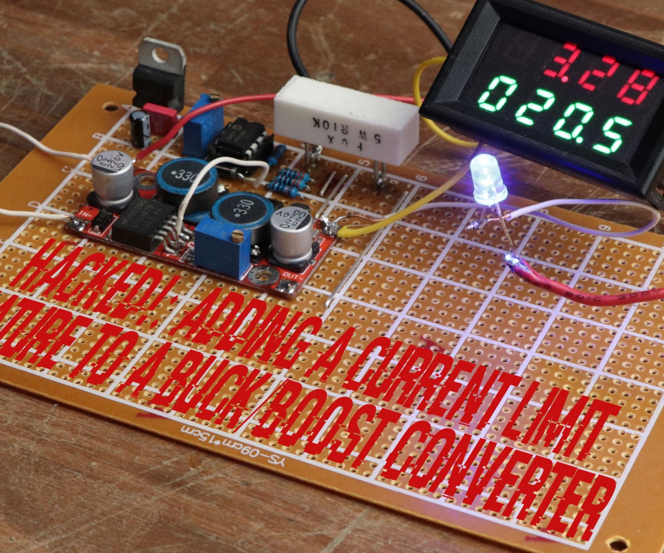
Power banks are usually 5 V. I've run LEDs from a power bank. I used a boost converter (**broken link removed**) and modified it to be constant current rather than constant voltage.
 
Power banks are usually 5 V. I've run LEDs from a power bank. I used a boost converter (**broken link removed**) and modified it to be constant current rather than constant voltage.
Hi Diver, would you mind sharing the constant current mod you made please?
I looked on the Googler, but could only find a lower quiescent current mod. (by Aka Kasyan)
 
Hi Diver, would you mind sharing the constant current mod you made please?
I looked on the Googler, but could only find a lower quiescent current mod. (by Aka Kasyan)

Your googlefu is weak young skywalker :D

 
I asked because I have the same MT3608's which were referred to in post #8.
GreatScott has quite a lot of additional parts, way more than the Weebly mod.
 
I asked because I have the same MT3608's which were referred to in post #8.
GreatScott has quite a lot of additional parts, way more than the Weebly mod.

The GreatScott one does more, and is variable current - the other is purely a constant current LED driver, and requires much more modification of the module (pretty impressive though!).
 
When I first designed the modification I did not take into account the possibility of one of the LEDs it was driving going open circuit. After a few months one of the 7 x 1 watt LEDs (Cheap ebay ones.) failed open circuit. As the regulator tried to do it's job of keeping the output current constant it destroyed the putput capacitor. The rest of the regulator board survived.

Les.
 
When I first designed the modification I did not take into account the possibility of one of the LEDs it was driving going open circuit. After a few months one of the 7 x 1 watt LEDs (Cheap ebay ones.) failed open circuit. As the regulator tried to do it's job of keeping the output current constant it destroyed the putput capacitor. The rest of the regulator board survived.

Easily done, interesting that the page above has taken account of that very issue - I've got an urge to modify one now - not that I've got any use for one! :D
 
Hi Nigel,
I did not create the web page until after I had the problem so that is the reason the zener diode is added. One strange thing is that when I created the web page the text of the modification was under the schematic. Now it is displayed to the right hand side. (It displays this way with Firefox and internet explorer. (I have just tried it with Firefox on an android tablet and it displays correctly.)
Les.
 
Status
Not open for further replies.

Latest threads

New Articles From Microcontroller Tips

Back
Top