Continue to Site

Welcome to our site!

Electro Tech is an online community (with over 170,000 members) who enjoy talking about and building electronic circuits, projects and gadgets. To participate you need to register. Registration is free. Click here to register now.

  • Welcome to our site! Electro Tech is an online community (with over 170,000 members) who enjoy talking about and building electronic circuits, projects and gadgets. To participate you need to register. Registration is free. Click here to register now.

Serial to Parallel

Status
Not open for further replies.

d1ck4

New Member
I'm new to electronics, and am trying to use a serial to parallel ic (TI SN74LV8153N) to light some LEDs. I've been having trouble, so in order to debug I've removed the serial portion of the project and am first trying to get the SN74LV8153N to drive all 8 pins (Y0 - Y7) high in order to turn on all LEDs.

The datasheet for the IC can be found here:
https://datasheet.octopart.com/SN74LV8153N-Texas-Instruments-datasheet-131714.pdf

Now according to the Function table if I hook outsel to low voltage, and OE to high then Yn (for n 0-7) should go high, but that isn't happenning.

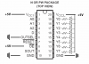
Here is an image showing how I have it hooked up:
schematic-gif.35273


I am using a 9V battery hooked up to a 5V voltage regulator to supply the power and ground lines. I've tried hooking up the extra pins to ground (I'm not really sure what the best practice is for unused pins), and have verified the leds are hooked up correctly (supplying a +5V current to the anode turns on the LED), and have used a multimeter to see that Y0-Y7 is at 0V. Is it possible that this is getting messed up because I'm delivering too much current to the IC? Any other ideas?

I'm a complete noob so feel free to tell me that I'm dumb, and where I messed up.
 

Attachments

  • schematic.gif
    schematic.gif
    25.1 KB · Views: 7,827
Typically unused Inputs are tied to ground (or in some cases Vdd) but there are special circumstances. For instance when a chips pins can be configured as inputs or outputs.

How are you trying to send data to the SN74LV8153N? The LEDs will remain off unless the proper data is sent to turn them on. What do you have the chips address set to? Does your serial data reflect that setting? Judging by your picture OUTSEL should be High.
 
Last edited:
Well I was just trying to get this IC to power the LEDs as a starting point. D is connected to ground at the moment, but the info in the function table made me think that if I set outsel to low, and oe to high, that the value of Yn would be high, regardless of what is input.

The reason i was doing this was because the circuit I made interfacing my PC to this serial to parallel IC wasn't working properly and I wanted to see that the IC was hooked up properly before trying to debug any communication issues.

The full circuit consists of a PC serial port connected to a Maxim max232CPE IC as shown in this wiring diagram I found online:

**broken link removed**

With TXD from the max232 hooked to D of the serial to parallel.

When I connect a pin to the +5V power line to force it high should I be using a resistor to limit current to the IC? What about when I connect it to VCC1, and VCC2... Should I be using a resistor there? Also I guess I don't understand the difference between the open collector vs the push pull output structures. Enlightenment would be greatly appreciated.
 
When I connect a pin to the +5V power line to force it high should I be using a resistor to limit current to the IC? What about when I connect it to VCC1, and VCC2... Should I be using a resistor there? Also I guess I don't understand the difference between the open collector vs the push pull output structures. Enlightenment would be greatly appreciated.

A resistor is not typically needed, either way. Open collector means the pin will only sink current or not, it does not output a high signal. The LEDs would have to be connected in the opposite direction in relation to your picture above and connected to Vdd not ground.

So you're connecting via a terminal on a PC? The datasheet does say the device is UART serial compliant but the data being sent is important of course. Are you just typing into the terminal? Are you sending data according to the chart in the datasheet?

**broken link removed**

You Must first send the device address and then the data. Have you tied the address lines to ground? Vdd?
 
Last edited:
As JimLovell says above:

"The LEDs would have to be connected in the opposite direction in relation to your picture above and connected to Vdd not ground."

Your data sheet indicates that when OUTSEL is low, as you have it, the Y's will be low, which means they are sinking current. I bet if you turn your LEDs around, you'll see some results.
 
I have tried tying A0,A1,A2 to ground. Here is a little C# app that counts to 255, 100 times that I was attempting to use to test the circuit. I believe I'm sending the data in the proper format. The datasheet says it's using 2 start bits, 1st one low, 2nd one is high, 7 bits of data, and then one stop bit. The api only supports 1 start bit and allows me to specify the number of stop bits and data bits so I'm sending 8 bits of data instead of 7 and forcing the 1st bit to be high (should have identical waveform to what the chip expects). Check out the function GetSignalBytes().

Code:
using System;
using System.IO.Ports;

namespace SerialToParallel
{
    class Program
    {
        static SerialPort ms_oSerialPort = null;

        static void Main(string[] args)
        {
            try
            {
                ms_oSerialPort = new SerialPort( "COM3", 9600, Parity.None, 8, StopBits.One );
                ms_oSerialPort.Open();
            }
            catch(Exception e)
            {
                System.Console.WriteLine( e.ToString() );
            }

            if(ms_oSerialPort != null && ms_oSerialPort.IsOpen)
            {
                try
                {
                    for(int nLoops = 0; nLoops < 100; nLoops++)
                    {
                        for(int n = 0; n < 255; n++)
                        {
                            byte[] aBytes = GetSignalBytes( (byte)n );
                            ms_oSerialPort.Write( aBytes, 0, 2 );
                            System.Threading.Thread.Sleep( 200 );
                        }
                    }
                }
                catch(Exception e)
                {
                    System.Console.WriteLine( e.ToString() );
                }

                ms_oSerialPort.Close();
            }
        }

        private static byte[] GetSignalBytes(byte n)
        {
            byte[] aBytes = new byte[2];

            aBytes[0] = (byte)((n & 0x0F) | 0x80);
            aBytes[1] = (byte)(((n & 0xF0) >> 4) | 0x80);

            return aBytes;
        }
}
 
It looks like the register you're using uses a very specific (and non standard) 10 bit serial frame two of which are needed to set all 8 bits, it's on page 3 of the PDF. I'm not sure if you can even generate that with an RS232 serial port?
 
Last edited:
Before you continue on the serial data side of things either switch your LEDs around and tie them to your positive power connection or set OUTSEL high by tying it to positive power.
 
Sceadian:
If you look at the program above, you'll see that it should be sending data in that format. It's faking it a bit, but it should be identical.

Code:
[FONT=Courier New]
What it wants:
[/FONT][FONT=Courier New]Start1 Start2 D0 D1 D2 D3 D4 D5 D6 Stop
0      1      X  X  X  X  X  X  X  1[/FONT]
[FONT=Courier New]
What I give:
Start D0 D1 D2 D3 D4 D5 D6 D7 Stop
[/FONT][FONT=Courier New]0     1  X  X  X  X  X  X  X  1[/FONT]
AllVol:
The datasheet on the 3rd row of the function table says Outsel Low, Reset X, OE High, Dn X, Yn = High in Open Collector mode (which means all Yn pins should be sinking current... Right?). Am I reading that wrong? Does "X" in that table mean it doesn't matter if it's set to high or low?

jimlovell777 / AllVol:
I tried hooking the positive end of the LED to +5V, the negative end to a resistor and then that resistor to Yn. Still no light.
 
Correct, X means doesn't matter/don't care. Putting little thought into the situation your program should never send any number lower than 128. The start condition is low followed by a high with 7 data bits and a stop bit. To create the high start bit 128+ must be sent. Your number range with a device address of 000 is 128 (all LEDs off) to 143 (all LEDs on).
 
Code:
private static byte[] GetSignalBytes(byte n)
{
    byte[] aBytes = new byte[2];

    aBytes[0] = (byte)((n & 0x0F) | 0x80);
    aBytes[1] = (byte)(((n & 0xF0) >> 4) | 0x80);

    return aBytes;
}

Yup. As you can see the data for both bytes is ored with 0x80, which sets the high bit to 1. So yes 128 would be the min value. For the first byte I'm taking the lower 4 bits and putting those into the lowest 4 bits of the data frame, and for the 2nd byte I'm taking the high 4 bits and shifting them into the low 4 bits of the data frame. In both cases each frame will have a high bit to fake the 2nd start bit, and then 3 0s for the address bits, and then 4 bits of data.

I program videogames for a living so the software stuff is something I understand... but the hardware stuff is what gives me difficulties. If I could at least see some lights on this thing then I could start to debug any errors with the program, but as is I'm poking around with a multimeter running out of ideas as far as how to debug the problem.
 
Last edited:
Thanks for the explanation dick, it was easy for me to ask than interpret the code at the time =)
 
Before you continue on the serial data side of things either switch your LEDs around and tie them to your positive power connection or set OUTSEL high by tying it to positive power.
Have you done this? It's important.
 

Attachments

  • LEDDrv.png
    LEDDrv.png
    22.2 KB · Views: 335
Last edited:
mneary:
I have tried that yes, but still didn't see any lights on the leds.

jimlovell777
I'm tearing this off the breadboard I have it on at the moment, and putting it on a larger one so I can clean it up a bit. I'll try tying reset high, and see if I can see SOUT ever goes high.
 
Status
Not open for further replies.

Latest threads

New Articles From Microcontroller Tips

Back
Top