Continue to Site

Welcome to our site!

Electro Tech is an online community (with over 170,000 members) who enjoy talking about and building electronic circuits, projects and gadgets. To participate you need to register. Registration is free. Click here to register now.

  • Welcome to our site! Electro Tech is an online community (with over 170,000 members) who enjoy talking about and building electronic circuits, projects and gadgets. To participate you need to register. Registration is free. Click here to register now.

Serial Data Out from 16f690 to 74HC164

Status
Not open for further replies.
Hiya,

Just a quicky,

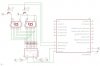
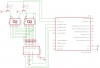
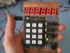
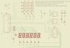
Never done any 'serial work' before but I'm going to experiment with driving a 7 seg display via a 74HC164 serial to parallel (HC595 would be better but don't have any yet). Would it be best to use the 16f690s' SSP module (which looks quite complicated for a noob such as me) to send out the data or just use a regular output?

**broken link removed**

Thanks in advance for any help.
 
The SSP module is really for the SPI and I2C forms of serial transmission.

Your really want to start with the Eusart module - while using a decoder chip to the seven segment is a good exercise , it would also be a good idea to do a tutorial like Nigels RS232 example, you just need a Max232 chip, 5 caps and a serial lead to you PC - you can then use Hyperterminal a see you data coming and going.

Be it SSP or Eusart that you use, the Datasheets info is terribly complex for anyone starting, so look around for simple good tutorials like Nigels - there are actually some good ones to be found on Microchips site - though as usual with them is a needle in a haystack job to find them.

eg https://www.electro-tech-online.com/custompdfs/2009/05/spi.pdf
 
You could use the SSP module if you want to learn to use it at the same time, but if you've not done much coding before it's probably good practice to just bit bang the shift register using a couple of I/O lines and some code. It's not terribly difficult, just compare each bit of the byte you're sending in series set the data line and enable on the shift register on and strobe the clock pin. Just make sure you meet the timing requirements for the shift register.
 
wow that bread board is over complex Why so many IC? Im sure you can do it all with 1 74HC164 and the Pic itself. Im sure with that kinda setup you can do 2 7 segs no problem.

Why use a decoder? You can do software decoding and then send it to the shift register. You can control the individual digits via transistors.

Ill make you a nice schematic so you can see how i would set it up.
 
The 74HC164 is an 8bit shift register, two 7segments is 14 control lines if you're running them right off the shift register so you'd need 2, or you'd have to multiplex it. If the shift register isn't a latching register multiplexing the 7 segments with it is going to create lots of nasty flicker so much I don't think it'd be usable.
 
Last edited:
ive never tried it but im sure a decent speed PIC and shift register wouldnt cause a bad flicker.
 

Attachments

  • 7seg.jpg
    7seg.jpg
    45.7 KB · Views: 1,601
The 74HC164 can run at speed up to 175MHz so i doubt a flicker will occur. Thats way faster than a pic can set a pin anyway. You can write to it as fast as a pic can write.

I just noticed its not a latch type tho. But thats always something obtainable :D

The "74HC595" would do it for you.
 
Last edited:
Hopefully Angry Badger followed all that =)
 
Never noticed how cool the 74xx595 was. I might buy a few now :D
(xx = LS or HC etc...)
Here is a schematic using the 74xx595.

Warning i chose to pullup SCLR/SCL to save a data pin on pic. Doing this will not allow you to do a 1 time clear on the register. But you can still just shift in all 0's and do a software clear.

G is pulled down because all of the work you are doing will require it low anyway.

If you have Eagle i also included the schematic file so you can see it better.
 

Attachments

  • 5957seg.png
    5957seg.png
    11.2 KB · Views: 968
  • 7seg.zip
    15.4 KB · Views: 384
Last edited:
I like the 7 segment led driver makes a good display and don't use a lot of pins.
 
Burt i love em too.

Since he is a beginner i feel like maybe he should do it in a way where he can get more experience and a better understanding of how micros work and coding.
 
Although learning to interface to the decoder is good coding practice as well, 6 of one half dozen of the other =) Either way it'll work. Since he's got the decoder setup arleady might as well use it.
 
Hi

Thanks for your replies, much appreciated.

The 'board' isn't really that complicated - only three chips including the pic (one chip unused). The 164 doesn't have a latch facillity as you correctly noted so I'm using a 74HC373. I'm only driving one digit to start with to see how I get on. It's almost working - display changes every time I press the button but it's garbled, think I messed up the connections or something. NP.

On my previous two projects I've driven the displays with parallel data, ccts / pics attached.

Thanks.
 

Attachments

  • Finished Clock 026 r2.jpg
    Finished Clock 026 r2.jpg
    262.5 KB · Views: 725
  • Clock schematic.jpg
    Clock schematic.jpg
    267.4 KB · Views: 1,816
  • Keypad_finished 003r2.jpg
    Keypad_finished 003r2.jpg
    271.3 KB · Views: 529
  • Keypad schematic.jpg
    Keypad schematic.jpg
    538.9 KB · Views: 1,065
Nice looking stuff dude. You cant be that much of a noob to do that. Good job.

Can you post some code ? so we can help futher. Also a schematic of what you are on now.

nice use of a 74HC373.
 
Last edited:
I press the button but it's garbled
If you hook the top two left pins on a 7 segment wrong you'll get a garbled display I done that a time or to
 
Hi,

I just figured why it's garbled. It's because I connected Qa from shift register to seg_a, Qb to seg_b etc. Needs to be the other way around Qa to seg_g etc., I think. Will play a bit more.

Won't post my code unless I get totally stuck. And I'm definately a beginner compared to most of you guys. I admire you experienced guys, your posts make great reading / learning material.
 
74hc373 Is Octal D-type transparent latch; 3-state you feeding it with the 74hc164 right. That the one that gets you every time.
 
Last edited:
I don't see why you "need" to use the latch? I use 595's because I bought hundreds as surplus, but I never use the latch for driving displays. Just clock the data in, that takes a couple microseconds then hold the data for the multiplex period. You wont see any flickering from the couple uS clocking the data in!

You only need 2 PIC pins, for data/clk.
 
Status
Not open for further replies.

Latest threads

New Articles From Microcontroller Tips

Back
Top