Continue to Site

Welcome to our site!

Electro Tech is an online community (with over 170,000 members) who enjoy talking about and building electronic circuits, projects and gadgets. To participate you need to register. Registration is free. Click here to register now.

  • Welcome to our site! Electro Tech is an online community (with over 170,000 members) who enjoy talking about and building electronic circuits, projects and gadgets. To participate you need to register. Registration is free. Click here to register now.

Sensing Connected Loads in 220v bus

Status
Not open for further replies.

mytech

New Member
Hi everyone,
Its my new project for my home.
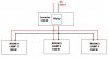
Please refer picture.
I have an 100w inverter and lets assume there are 3 rooms with 3 100w lamps.
While the power is live it will supply power to every load.
If power goes i can use anyone lamp at a time since my inverter is 100w.
Usually we used to connect anyone partcular lamp with it.

But i just want to turn ON anyone at a time.

1. So when power goes OFF i have to switch OFF all my loads and switch ON my inverter manually after that i can switch any one lamp, this is one method.

By mistake if switch it ON my inverter with two lamps, my inverter will burn. I can keep overload breaker for this.

But All i need is, i want to calculate the loads connected to load before switching ON my inverter manually.

1. My idea is i can send 3v dc supply to 220v AC bus when power goes OFF, so that if i switched OFF all my loads there wont be any return of 3v so my LED will not glow in my inverter side then i can allowed to switch on my inverter. if glowing means some lamp is still connected, i can check untill LED goes OFF.

I am just telling my basic idea, but for real scenario there are lots of loads will be connected to 230v bus, even i can switch it OFF all but i want to ensure all the loads are disconnected before switching ON my inverter, but i cannot do anything with power indicator and few loads. So LED method will not work, i cant stop LED glowing.

So, Is there any other method available, shall i send particular frequency and compare with return frequency?.. anyone have idea, please suggest me.
Thanks.
 

Attachments

  • Inverter.jpg
    Inverter.jpg
    19.4 KB · Views: 276
hi mytech,

The problem with the 3Vdc test supply is that you will read back thru the inverter output winding.
 
Mytech,

What's the maximum current draw on you system when running under normal power? Are there any loads that switch on and off by themselves...like heaters...so, may appear to be off, but only at that moment?

ken
 
Hi ericgibbs,
Thanks for your "10000th" post to my thread.
Keep your valuable support as long as possible, Congratz!!!

Then LED test is an simple idea only just injecting volt through phase line and reading in neutral line, if closed i will gt the same volt. For only 3 lamps it will work. But there will be lot of loads connected to bus. So i am in need of some other method to identify the connected loads.


@KMoffett
Actually the current would be around .45A, Basically i just need to calcuoate the connected loads to switch ON inverter. While enhancing i can consider these kind of automatic switching load and all.

My suggestion is i have switch all kind of loads or else my over load relay will get activated and will switch OFF inverter if sudden loads hike.

First lets identify the simple method to sense the connected loads to 230 bus.
Thanks.
 
OK, this circuit will let you detect the presence of load(s) >0.1mA AC.

For detecting different levels of current draw, you might want to look into "current transformers".

Ken
 

Attachments

  • Line Detector.gif
    Line Detector.gif
    15 KB · Views: 619
Last edited:
Thanks for your circuit, but the reqirement is before switching ON my inverter i have to sense whether all loads are disconnected or not. After giving power via inverter i can use this current tranformer everything to protect inverter.


But how can i identify simply, all loads are disconnected from the bus before switching ON inverter?.. So current not gonna play any role before switching ON inverter. I just want to inject something and compare the return with the source, If i am not getting anything then there is no load connected to bus, i can switch ON my inverter but practically not possible, thats wat asked frequency will work??

Thanks.

hi,
If you have 3 loads, lamps, you could use a 47R and 220nF cap with 1N4006 diodes to drive a low voltage relay, at say two of the loads.

The two lamp turn on switches would latch in the relays, at power fail the relays would drop out and auto switch off the two lamps.
The third lamp would relight when the power was restored.

Do you follow OK.?:)
 
I made the assumption, because of the relay, that the loads were being continuously supplied by the 230vAC bus. And when the bus failed you would manually or automatically (with the noload qualification) switch on the inverter. My circuit would be used to indicate to some device that there was a load prior to the buss failure.

If the relay completely isolated the loads from the buss...and the inverter...you could just ohm-out the load circuit.

Ken
 
Last edited:
@ericgibbs
You have givena a good idea, i never thought of this electronic switch.
But for explanation purpose of my idea, i took 3 lamps as basic example. There would be switch boxes at each room, there might be cell phone chareger connected to it or some other devices even TV or some thing.

If i tell my parents to switch OFF all loads when power goes OFF before switch ON inverter, they do so. But they might forget to switch OFF few loads mistakely, thats wat i need an indicator, near to inverter switch. For that i have to keep some circuit.
Hope you understand my real scenario.
Anyway i will implement ur circuit idea in someother application. Thanks !!!

@KMoffett
"Ohm-out the load circuit" , i guess that will work, how can i implement that in my application?, any similar elecronic circuit is there, to perform same process?
 
Status
Not open for further replies.

Latest threads

New Articles From Microcontroller Tips

Back
Top