Continue to Site

Welcome to our site!

Electro Tech is an online community (with over 170,000 members) who enjoy talking about and building electronic circuits, projects and gadgets. To participate you need to register. Registration is free. Click here to register now.

  • Welcome to our site! Electro Tech is an online community (with over 170,000 members) who enjoy talking about and building electronic circuits, projects and gadgets. To participate you need to register. Registration is free. Click here to register now.

SCR switching

Status
Not open for further replies.

nvisser

New Member
Hi
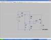
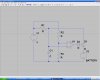
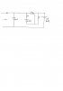
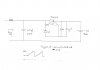
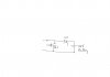
Can anybody tell me how to switch a scr on, to dicharged a capacitor into a battery as soon as the voltage in the capascitor reach a certain voltage, say 23V. The cap gets charged from a external generator and bridge rectifier. See diagram
 

Attachments

  • scr switching.jpg
    scr switching.jpg
    269.6 KB · Views: 1,353
Last edited:
Well, just a few things that hit me.

One, you really ought to be charging the cap through a resistor.
That arrangement can be used to bias a transistor when the potential across the capacitor reaches your desired value. The transistor could switch your SCR I suspect.

I've never designed an SCR circuit but I imagine this is the gist of it.
 
Something like this might work. R2 and R3 sets the level to fire the SCR, which is modeled by D1. I'm not an expert in SCR circuits either, so I encourage you to continue to get input.
 

Attachments

  • CapScrBattery.JPG
    CapScrBattery.JPG
    80.8 KB · Views: 1,498
The anode is the positive lead on a SCR. An SCR blocks in both directions when off and conducts in the forward direction when fired. Thus the cathode would need to be connected to the battery plus terminal in BrownOut's circuit.

The gate of an SCR is referenced to the cathode, so if the cathode is connected to the battery + terminal the gate trigger voltage must be equal to the battery voltage plus the gate firing voltage. In that configuration you would also need a diode in series with the gate to avoid excessive reverse bias of the gate from the battery voltage.
 
Heh! Well, I didn't have the patience to look through all the libs for it. One other thing, the SCR might be sustained through R1 in my diagram. Careful attention should be paid to this resistor value to advoid that situation.
 
Op amp comparator is a good idea
I was thinking maybe more in the line of a zener . I saw a circuit using a 5m pot and 101 cap to the gate . I used a triac but could not get it to trigger
 
It gets easier if you define it so that the SCR triggers when the capacitor is at a specified voltage greater than the battery. Suggestions so far have addressed your original requirement assuming you meant the 23v was referenced to (V-).

Your original circuit would work, with a zener from the SCR anode to the SCR gate, A resistor (1k) from gate to anode is also suggested to reduce false triggering. A resistor (100R) in series with the zener might be a good idea to limit gate current.
 
Thank you. Do you mean like on this diagram?
How will I choose the value of the zener?
Can you please describe how this circuit functions
 
Last edited:
My bad!!! I said resistor from gate to anode, I meant gate to cathode.

If you want the circuit to trigger at 23V, the zener would be (23 - 12 - 0.5) = 10.5V. (Nearest value might be 10V +/- 5%.). The 0.5V is approximate for the the gate voltage. Recalculate if your battery voltage will be different (like 12.8, etc.).
 

Attachments

  • scr switching.jpg
    scr switching.jpg
    262.5 KB · Views: 901
Great. I will try it a bit later. The previous did not trigger.
Does the same applies when using a triac (bd136)
 
I cannot get it to pulse. I want it to trigger when the cap reach about 24v . It should then discharge into the battery and as soon as the voltages on the cathode and anode are about the same(( around 12v) it must switch off and only trigger again when the cap reach 24v. Like a pulser. It can be done with a adjustabler timer but there must be a easier way.
 
The SCR may take more current on the gate to trigger than the comparator can provide. Check the datasheets and see if you need to drive the SCR with a current limited BJT/FET
 
Hi Guys. It`s working!. Thank you all for your inputs
I received my scr`s today. TYN612
The cap I use is a 470uf, 250v and it is getting charged by a many turns 27 # wire coil that is just made stand on top of the Bedini trifilar coil. At this stage it triggers at around 36v as the zener I use is a 24v.
I will post a schematic on Monday when I can scan the picture
In the meantime I will describe it. It was built around the description from Mneary from this forum: https://www.electro-tech-online.com/threads/scr-switching.98989/
A 390 ohm in series with the zener from anode to gate
A 0.1uf (104) cap in parallel with a 470 ohm resistor from gate to cathode
Cathode connect to batt +
Anode connect to 470uf +
It charges up to 36v in about 2 sec and then it discharge into the battery
Also see:**broken link removed**
 
Last edited:
Here is the final circuit. It`s been tested for the whole weekend
The 0.7v drop must be between the gate and cathode and not like on the diagram
 

Attachments

  • scr switch001.jpg
    scr switch001.jpg
    386.7 KB · Views: 1,121
Last edited:
Status
Not open for further replies.

Latest threads

New Articles From Microcontroller Tips

Back
Top