Continue to Site

Welcome to our site!

Electro Tech is an online community (with over 170,000 members) who enjoy talking about and building electronic circuits, projects and gadgets. To participate you need to register. Registration is free. Click here to register now.

  • Welcome to our site! Electro Tech is an online community (with over 170,000 members) who enjoy talking about and building electronic circuits, projects and gadgets. To participate you need to register. Registration is free. Click here to register now.

Schmitt trigger IC output goes below zero question

Status
Not open for further replies.
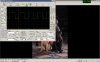
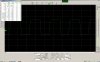
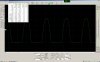
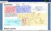
I have a Colpitts crystal controlled oscillator on about 460kHz. The slow rising edge was not triggering a divider reliably so I added a Schmitt trigger IC, capacitively coupled to the buffer amp collector, of Q2 and biased 50 / 50 across the 5V and ground rails with two 10k 1% tolerance resistors.Whilst the resultant waveform is square and clean it drops below zero. Why is this, it also does it without the bias resistors, and DC coupled, and is it of concern please. I am bread board testing it without the divider. The files are with the Schmitt trigger, at its output pin,no divider. The schematic, without Schmitt, and the output at the collector (despite the wrong file naming....) of Q2 without the Schmittor divider. Probe is at X10. The interconnecting leads are a bit long and just ordinary wires.

Thanks.
 

Attachments

  • lf-schmitt-on-collector-q2.jpg
    lf-schmitt-on-collector-q2.jpg
    548.9 KB · Views: 99
  • lf-emitter-q2-r16-at-10k.jpg
    lf-emitter-q2-r16-at-10k.jpg
    572.4 KB · Views: 101
  • schematic2.jpg
    schematic2.jpg
    238.5 KB · Views: 99
If your Schmitt trigger chip is powered from +5V and GND, I don't see how its output can possibly be going below GND. The only possible cause for what you're seeing, IMO, would be a X10 scope probe that isn't properly adjusted. I just don't know what else it could be.
 
I doubt you need a Schmitt trigger. I think the problem lies in the biassing of Q2. With R15 only 1K, Q2 is not conducting, and even if C12 is driven with a full 5V amplitude signal the Q2 collector voltage does not reach the logic high threshold reliably. Try increasing R15 to 3k3 or even 3k9. LTspice indicates that should do the trick.
OscOutput.PNG
 
The issue is I have modded the thing to run on LF so the rising edge is slow and not very sharp, but for sure I will try fiddling with the bias, perhaps with a pot initially. I see what is meant by impossible to go below ground with the single supply, maybe it's a grounding issue as the lead lengths are long as the Schmitt is on a separate bread board for trialling. Many thanks :) Very good of you to model it!!
 
Like the reply on the other website, why not make the oscillator with the Schmitt trigger IC?
 
Looks like you have an issue with lead/trace stray inductance and/or impedance mismatch.
Edit: Scratch that I re looked at your scope traces, I see there are flat areas below ground, initially I'd be looking at a high ground resistance ground track or connection, or bias as alec said.
 
That is what happens when it is built on a solderless breadboard with poor and intermittent connections.
 
That is what happens when it is built on a solderless breadboard with poor and intermittent connections.


I'd like to but the only places that stock it want £12 + for postage to me here in the UK, and I am a bit of a tight old git :)
 
Looks like you have an issue with lead/trace stray inductance and/or impedance mismatch.
Edit: Scratch that I re looked at your scope traces, I see there are flat areas below ground, initially I'd be looking at a high ground resistance ground track or connection, or bias as alec said.


I think it's a scope grounding issue due to trailing wires and a bread board! Thanks for the replies :)
 
Touche I'm a tight old git too, but I thought they were generous down is Shropshire!

I have a offline switcher on breadboard right now, it works but doesnt produce the current its designed for, I didnt expect it too, if I wiggle the I sense resistor available current goes up, breadboards are only good for 100mA or so.
 
Contacts and tarnished jumper wires on breadboards are intermittent. You could waste many hours solving problems caused by one. The many rows of contacts and jumper wires are antennas that pickup interference and have capacitance coupling that messes up many circuits.
 
Whilst the resultant waveform is square and clean it drops below zero.
Are you sure? To me it looks like a normal waveform on a scope with either the zero (DC balance) adjustment or the vertical position a bit off.

ak
 
Are you sure? To me it looks like a normal waveform on a scope with either the zero (DC balance) adjustment or the vertical position a bit off.

ak


Yes, the numeric display shows 500mV negative. It was poor grounding, I tidied things up a bit and it's fine now, thanks for all the info and help.
 

Attachments

  • better-grounding.jpg
    better-grounding.jpg
    474.6 KB · Views: 79
Status
Not open for further replies.

Latest threads

New Articles From Microcontroller Tips

Back
Top