j00ooo00an
New Member
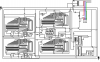
hello!! please help me with our project design.. i need an schematic diagram for a digital clock.. but we were given only 2 weeks from now to prepare.. below is the statement of the problem given to us by our instructor.
design a combinational circuit that will simulate the capacity of the digital clock to tell the current tme of the day. the design must be further more flexible enough such that it will have the capacity to be set to different time level should there be in consistencies with the displayed time and the actual time.
another design specfication is for time to be displayed in the standard format and not in the GMT (Greenwich Mean Time) format. microswitches should be employed as input transducers for the set/reset switches and the 555 astable multivibrator may be used in the generation of the 1 second clock pulse though other pulse sources are also preferable.
the second, minute, and hours parameter should be displayed, hence it follows that there should be at least six seven segment.
ill be waiting for replies..Thanks a lot.")
design a combinational circuit that will simulate the capacity of the digital clock to tell the current tme of the day. the design must be further more flexible enough such that it will have the capacity to be set to different time level should there be in consistencies with the displayed time and the actual time.
another design specfication is for time to be displayed in the standard format and not in the GMT (Greenwich Mean Time) format. microswitches should be employed as input transducers for the set/reset switches and the 555 astable multivibrator may be used in the generation of the 1 second clock pulse though other pulse sources are also preferable.
the second, minute, and hours parameter should be displayed, hence it follows that there should be at least six seven segment.
ill be waiting for replies..Thanks a lot.