Continue to Site

Welcome to our site!

Electro Tech is an online community (with over 170,000 members) who enjoy talking about and building electronic circuits, projects and gadgets. To participate you need to register. Registration is free. Click here to register now.

  • Welcome to our site! Electro Tech is an online community (with over 170,000 members) who enjoy talking about and building electronic circuits, projects and gadgets. To participate you need to register. Registration is free. Click here to register now.

sawtooth Generator Circuit

Status
Not open for further replies.
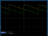
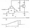
I appreciate your responses. I tried the previous circuits provided but as you all know they are not a very good sawtooth generator. However, I am exploring the one below. It is good up to 20k Hz but beyond that point the signal dies completely out. I will keep on working on it. Any help will be highly appreciated.
 

Attachments

  • sawtooth generator.jpg
    sawtooth generator.jpg
    37.6 KB · Views: 6,898
Hi there,


How accurate do you need this thing? That's a major part of the decision on
what kind of circuit can be used. If you are not sure, perhaps you can tell
us about your intended application and we can recommend something.

For example, a 555 timer ic with a transistor connected as a constant current
generator that charges a cap can be used to some degree.
 
if you want a slower perfect saw tooth you could try "synthesizing" it with a pic, but being a digital representation of an anlog waveform the clock speed to analog frequency ration will be high: running a pic at 20 MHz might do it at it would give you 40 steps in your half a MHz output, I did this when fooling around but was running at 8 MHz and did not get above 10 KHz in my experiments, I used the PWM output.

another way is to have an DAC and use a counter IC so you can make the counter count from 0 to whatever (depends on your idea of perfection) and the digital to analog converter will output the rising voltage until at the top it will go straight back to 0 and start counting again, I think using a low pass filter output and 4-6 bits of resolution you will get about as near perfect as practicl and possible without having an over complex circuit.

what do you need this for ?
 
I would like it to be perfect. It should be at a frequency of 500k Hz. It will be used to compare it with a low frequency sinusoidal signals to achieve a pwm output signal. So far I am still working with the sawtooth. I am knowledgeable with pic pic16f690 andpic16f887! Thank you
 
I would like it to be perfect. It should be at a frequency of 500k Hz. It will be used to compare it with a low frequency sinusoidal signals to achieve a pwm output signal. So far I am still working with the sawtooth. I am knowledgeable with pic pic16f690 andpic16f887! Thank you


Hi again,


Are you sure you dont want a triangle wave instead? Is this for sine synthesis?
 
Last edited:
hang on a minute !!! just how much do you know about what your doing ???

if your trying to generate a PWM version of a low frequency then why not use a pic in the first place ? its a simple program to use the ADC values to determine the duty cycle output, just a couple of lines of code. of course you are in the same boat again for the speed, perhaps if such a speed is really neccesary (again do you know you really need it ?) you could get the fastest pic possible say a 40 MHz

Sawtooth wave - Wikipedia, the free encyclopedia

Pulse-width modulation - Wikipedia, the free encyclopedia

I completely understand the contents within the links given above. However, it has been a while since I design discrete circuits to accomplish the periodic waves shown in the links above. I would really appreciate if feedback can be provided to assist me in building a high speed sawtooth generator with a frequency of 500kHz. Thank you
 
I think there is a chip out there that is a sort of "function generator" and will make square, sinusoidal and retangular waveforms with the option to vary the duty cycle, you could use the triangle output with a 100 % duty cycle I beleive but I'm not sure what the chips top speed is and what its number is maybe 8036 ?

is this for audio application ? if so surely you can lower the frequency, that would make looking for parts much easier, at present your looking for something more perfect than you probably need and you in for a rough and exspensive ride

It will be for a pure DC to AC power inverter. I built one in the past but it used a lot of microchips. I now would like to build one by using all discrete circuits. It is fun.....Thank you for your responses:)
 
err surely even just 1 KHz is enough then ? that 200 steps in every cycle more than enough, your going way over the top and making it more complicated than it need be. If you put the PWM through a low pass filter it will very acurately reconstruct the sine at 1 KHz sample rate on a 50 Hz signal.
 
If you are just using the sawtooth to generate a PWM, then it doesn't have to be perfect. A 555 and comparator will give you a great variable PWM output.
 
Last edited:
If you are just using the sawtooth to generate a PWM, then it doesn't have to be perfect. A 555 and comparator will give you a great variable PWM output.

I agree. Another option is to take the signal directly off the timing capacitor. Yeah, it's a little crooked, but still a pretty good approximation.
 
Well I tried to get to get 500KHz out of a PUTJ 2N6027 and only got up to 211KHz and that was with 3 10pf caps in series. Scope shot attached,
I also said that if you charge a cap with a constant current you would get a flat ramp instead of the rc time constant ramp, not so sure now, I know I have in the past but I couldn't do it today. I put a resistor in the circuit and measured the amps and took a picture of it, then replaced the resistor with a 3 terminal current regulator LM334 and adjusted it to the same current and took another picture, put the on the same picture, attached.
Kinarfi
figured out why I wasn't getting a nice straight ramp, I was using the AC coupling tracer instead of the DC coupled tracer. I use current regulated cap charge ramps fairly often and get nice straight ramps.
here's and example,
kinarfi
 

Attachments

  • sweet spot 8.84v.png
    sweet spot 8.84v.png
    11.4 KB · Views: 394
Status
Not open for further replies.

New Articles From Microcontroller Tips

Back
Top