Continue to Site

Welcome to our site!

Electro Tech is an online community (with over 170,000 members) who enjoy talking about and building electronic circuits, projects and gadgets. To participate you need to register. Registration is free. Click here to register now.

  • Welcome to our site! Electro Tech is an online community (with over 170,000 members) who enjoy talking about and building electronic circuits, projects and gadgets. To participate you need to register. Registration is free. Click here to register now.

safe LED Voltage

Hi Guys,

I'm having a brain freeze at the moment.... hence this question....

I'm wiring (or at least trying to) my own UV LED exposure unit. It contains many many many many LEDs (I was going to try for double sided, but that would involve like 500 LEDs, so maybe not!).

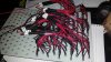
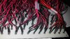
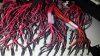
I have struggled using prototyping boards for making the panels for the exposure unit, so instead I have bought pre-wired LEDs (these come with 20cm tails and aa limiting resistor) which I have been bunching into groups of 20 parallel LEDs.


Still with me? so I now have over 200 LEDs bunched into groups of 20. however if I were to put the bunches in parallel with each other, the current draw on the psu would be HUGE like several amps... which I'm just not happy/comfortable with.

If however I put several of the bunches in series with each other, I reduce the brightness (and I assume intensity) if the UV light. this can be compensated by upping the supply from 12v to 20v.

However I am concerned that that will damage the LEDs in the longer run....

The attached image shows what I'm getting at... if I put all the bunches in parallel, I have high current, if I put them in series (more like parallel series mix) I need to up the voltage, which as I can't change the current limiting resistor I'm concerned about damaging the LEDs


If I can't work a solution, I will have to ditch the idea and buy a UV Tube exposure box.

Cheers everyone.

Owen.
 

Attachments

This would likely go much better if you could provide the data sheet for the UV LED Panels that you have and are using. Just using two panels as an example. If I go buy two panels and each panel is rated at 12 volts 700 mA then each panel is about 8.4 Watts. For normal operation if I want two panels they would generally be placed in parallel. The voltage remains at 12 volts, my current increases to 1.4 Amps and my power is now 16.8 Watts. If I want to run my panels in series I need to increase my voltage top 24 Volts to maintain my 16.8 Watts. All comes out in the wash as 12 volts at 1.4 amps or 24 volts at .7 amp is the same 16.8 Watts. You can't place two 12 volt loads in series with a 12 volt supply, you need to increase the supply voltage to 24 volts. Personally I would just parallel your panels and make sure your supply can provide the needed current.

Why are you concerned with the current?

Ron
 
Hi Ron,

I'm making the LED panel myself, and am using UV LEDs bought from EBay with 20mA If, there is no Vf rating listed, but they come with a 470 Ohm limiting resistor, so that make a rough Vf of 3.5v.

they are sold as individual LEDs (so each one has the limiting resistor), which I then bunch into 20, then am connecting together.

I'm worried about the Amps cause I don't want the thing to catch fire!!! Just worried too much current may melt the cables etc, and I'm really not used to that high a current in any of my projects.

I'm struggling to work out the sums of 20 parallel LEDs in series with 20 other parallel LEDs in series with 20 other LEDs.... I just dont want to go to the effort of wiring it all up for me to burn them out in no time....

Owen
 
I'm making the LED panel myself, and am using UV LEDs bought from EBay with 20mA If, there is no Vf rating listed, but they come with a 470 Ohm limiting resistor, so that make a rough Vf of 3.5v.

Sounds about right for the few UV LEDs I have seen. Typically a Vf of around 3.0 to 3.5 Volts and a If of around 20 to 25 mA. So using your numbers here is what I would do. I would place 3 LEDs in series with a 75 Ohm resistor. If we figure Vf = 3.5 then 3 x 3.5 = 10.5. That gets us (with a supply of 12 volts) 12 - 10.5 volts / .020 amps = 75 Ohms. You have 200 LEDs if I read this right. I would build using strings of 3 LEDs each with a single 75 Ohm resistor per string. Making 33 strings in parallel would be 99 LEDs in a panel that would draw about 20 mA per string x 33 strings = 660 mA and two such panels (or one large one with 198 LEDs ) would only draw about 1.32 Amps. Considerably less than two amps total at 12 volts. I would fuse it at about 2 Amps and use a supply capable of 12 volts 2 amps. If the Vf and If are right, this should work out just fine.

Unfortunately if what you have for LEDs are already pre wired with each LED having a current limiting resistor connected my suggestion may not be all that easy to build.

I'm struggling to work out the sums of 20 parallel LEDs in series with 20 other parallel LEDs in series with 20 other LEDs.... I just dont want to go to the effort of wiring it all up for me to burn them out in no time....

If you have twenty parallel LEDs at 20 mA the I total would be 400 mA. The problem starts when you start placing them in series. If we figure a single LED is Vf = 3.5 and If = .020 then 12 - 3.5 = 8.5 / .020 = 425 Ohms. Thus the 470 you mention. If I start placing things in series I need to double the voltage and I would have a LED, Resistor, LED and Resistor in series. Not a good way to go about things.

Ron
 
OK,

I think my main brain freeze is over (sorry I usually am much better at this than this post may suggest)..

The images show what I have currently, and you can see why i'm worried about high current (or higher than normal), mainly because of the amount of heat that will be generated, even for a short time of use.

putting the LED's in series does end up with Resistor->LED->Resistor->LED etc.. which as you says although its not going to damage the LEDs isn't great.

my best bet, even against my initial thoughts is to run everything in parallel.... 256 x 20mA = 5.12A (thats only 1 panel), and a lot of heat....

I'm trying to make the panels A4 size, with the LEDs being 1 cm apart (on center) I'm starting to think thats too much overkill, but i'm too far in to stop now...
 

Attachments

  • 20141129_041117.jpg
    20141129_041117.jpg
    381.4 KB · Views: 227
  • 20141129_041131.jpg
    20141129_041131.jpg
    378.5 KB · Views: 237
  • 20141129_041135.jpg
    20141129_041135.jpg
    450.7 KB · Views: 225
As to heat, if you are concerned just add an 80mm generic computer chassis fan to your box.

Lets take a look at something:
LED Strings.png


We have two strings of LEDs. The first (left) string uses a LED having the Vf of 3.5 volts and If of 20 mA. The string current is 20 mA with 12 volts applied. The series resistor is 425 Ohms. R1 is dissipating 170 mW of power and the string dissipates 0.170 + 0.070 = 0.240 Watts. So I have a little single LED in a circuit dissipating a total power of 240 mW. Now look at second string (right). R2 is only dissipating 30 mW and each of the three LEDs is dissipating 70 mW for the same total power of 240 mW. If I were to run 99 of the first string I would be using 99 x .240 = 23.76 Watts but to get the same light I would only need 33 of the second string so 33 x .240 = 7.92 Watts or about 1/3 the power. All the wasted power is heat.

The images you posted are very good. Looks like some overkill with the wire diameter but all things considered you are doing a good job. Even if we took what is shown in the first string and placed 100 or 200 in parallel (one hell of a job) we would get 2 or 4 amps respectively which really isn't much. I wouldn't worry about it. There is also a down side to the design on the right. In the unlikely possibility a LED should fail shorted the string voltage across the remaining two LEDs will increase as will their forward current.

Since you are so well committed I would continue to march. I only say this because of how far along you are. In reality your 470 Ohm resistors will be dissipating more power than your LEDs will. Your maximum current isn't that much and I wouldn't be concerned. Just use good design practice and fuse it. If it runs warm then just add a fan. Things will work out fine.

Ron
 
Last edited:
I agree with the above.

However I would like to add a few links which you (or others) may find useful in future.

First my friends website where he has built several caving lamps for photography including a UV floodlight http://www.superpants.net/

Secondly the Big Clive website which made the PCBs used in my friends floodlight http://www.bigclive.com/flud.htm, two PCBs fit nicely into a 500W floodlight enclosure.
 
Responding directly to the title of the TS first post:

The safe LED (forward) voltage is whatever it has to be to keep the current below the max allowed current
.

Note that the correct way of accomplishing this is to control the current through the LED, and then the forward voltage will take care of itself....
 
Why have so many resistors when only one resistor is needed when LEDs are in series??
Cut away the resistors and connect a bunch of LEDs in series and in series with ONE resistor calculated for 20mA.
 
The resistors were part of the pre-wired-ness, I was trying to save time buying pre-wired, I kinda hoped there wouldn't be a resistor attached... :(

I was just worried, wring them all in parallel, would create a large current draw, which i was afraid was too much.... it seems as if my worries were mainly wrong. I was also worried about putting led's in series with the resistors in the way (I really really really didn't want to re-wire the LEDs otherwise i just hadn't saved any time, and I didn't have the patience to do so with soooooo many LEDs.).


As it is, i have finished the panel with 256 LEDs in parallel..... the actual physical current draw is yet unknown as my bench top PSU only supplies a max of 3A.


Misterbenn, those panels look awesome, and I will certainly keep my eye on them if I change anything, kinda wish I'd known about them first!!

Owen.
 
Why have so many resistors when only one resistor is needed when LEDs are in series??
Cut away the resistors and connect a bunch of LEDs in series and in series with ONE resistor calculated for 20mA.

Well because when he bought the parts he bought 200 LEDs and each one included a series resistor for use with 12 volts. Looking at the pictures he posted we can see he began building and is well along with building using a series resistor with each LED. So his options are pretty simple in that he can gut everything as seen in the pictures and remove all those resistors and make it like the right half of my cartoon or continue with what he has already done. While hindsight is always 20/20 that doesn't help him much right now. So he has two options, either gut things and start again or go with what he has which is inefficient. Been a few days so beats me where he is at with things.

<EDIT> OTM was quick on that. :) </EDIT>

Ron
 
Simple arithmetic shows that each 3.5V LED in series with a 470 ohm resistor draws 18mA from 12.0V. Then 256 of them draw a total of 256 x 18mA= 4.6A.
Each resistor heats with 0.152mW so the total heat from 256 of them is 38.9W which is a LOT of heat.

If groups of 3 LEDs are in series with a 75 ohm resistor then the total current will be 1.7A and the total heat in the resistors is only 2.6W.
 
whilst I agree with your comments about the heat, and the maths is helpful, I was stuck in terms of what I had options to do.... I originally planned to put the LEDs onto a stripboad, in groups of 3, with a 75Ohm resistor but I had no end of issues soldering them up in the way I wanted, in the density I planned (probably overkill, but it is A4 in size my panel).


I went for pre tailed LEDs but they came with the resistor in tow.... which I hadn't planned....

the crux of this question was more along the lines of putting several LEDs in series, but with a resitor between each one....

I've finished the panel now, so hindsight is hindsight... I may use the superflux boards linked above in the future, but not this time.....

Thanks for everyones help all the same, I should have been able to answer this myself, but I couldn't for some odd reason of a mental block.

Owen.
 

Latest threads

New Articles From Microcontroller Tips

Back
Top