Continue to Site

Welcome to our site!

Electro Tech is an online community (with over 170,000 members) who enjoy talking about and building electronic circuits, projects and gadgets. To participate you need to register. Registration is free. Click here to register now.

  • Welcome to our site! Electro Tech is an online community (with over 170,000 members) who enjoy talking about and building electronic circuits, projects and gadgets. To participate you need to register. Registration is free. Click here to register now.

RS232 master/slave unit

Status
Not open for further replies.

Top Cap

New Member
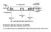
Hi Folks, with reference to the attached, I have to make a unit that can allow 6 master units to control 6 slave units via one RS232 link. Only simple on/off commands are required so that if the Master is turned on then its corresponding slave is switched on. If the Master is turned off then so is its slave. Master turned on is signified by a low voltage supply fed to an opto isolator. The slave is controlled by a simple relay contact, open = Off.
I have to design something to fill the Green boxes, the Red box is the gear I have to interface to and is a 6 way RS232 multiplexer talking to a de-multiplexer some distance away via fibre optic cables.
I only have one of these multiplexed channels to use, the others are used for data linking.
I have ruled out PICs as I have no programmer and willing to craft the Green box electronics with off the shelf chips. Something tells me there may be an easier way without UARTS. One of the headaches is making sure that the right Master talks to its own slave and no other, also the status of the Masters must be accurately mirrored at all times by the Slaves. Anybody have any ideas? Perhaps someone on the Forum has had a similar problem to solve?
Best Regards
Les
 

Attachments

  • rs232 coupler.JPG
    rs232 coupler.JPG
    58.1 KB · Views: 758
So basically, you want to re-create the 6 channel multiplex/demultiplxer in the green box???
 
Yep, take eight on/off feeds, convert the parallel data to a serial stream by way of a UART and send out as RS232 to allow interfacing with the proprietary RS232 optic equipment shown within the Red box. Then do the reverse to allow each of the eight fore mentioned inputs to control their respective Slave units.
The fibre optic link boxes are RS232 input/output and already in use so I have to use the same standard.
Serial Comms is not really my subject, I assume it is OK to have the UART continually sending so that any real time changes are picked up.
 
I was hoping that it would be possible to use one bit per Master control, producing a Mark or Space as necessary and for this to be reproduced at the receiving UART, all done asynchronously without handshake.
If this is a mad idea and cannot possibly work then I shall have to think of another method. Hence the post, I suppose I am looking for some kind of assurance in case I go down the wrong path.
Regards
Les
 
I'm sorry if I'm not getting it. To switch 6 circuits, you'll need 3 bits minimum. The protocal can be something like this:

Slave 1 - 000
Slave 2 - 001
Slave 3 - 010
etc.

Just switching to each slave using the first 3 bits of a packet would be pretty simple. You simple need to capture the first 3 bits of each packet and feed them into a de-multiplexer. The next bit can be the control bit, and then the receive can just ignor the rest. It can be done with simple digital chips, you just have to work out the logic.
 
Hi BrownOut, does the attached drawing help?
It would make decoding at the other end very easy :)

Oh! Most Important, data comms is only one way i.e. Master to Slave.
No reply path is required.
 

Attachments

  • Data output.JPG
    Data output.JPG
    30.8 KB · Views: 588
Last edited:
Then I think you just need a register to hold each of the slave bits, and connect slave to it's respective register. If you use a UART, just connect each slave to one of the 8 data i/o's. If your using something else, just do a serial to parallel conversion, and connect the slaves.
 
Many thanks for your help and encouragement, I just have to sort out the nasty bits like ensuring the Slaves are all turned Off if data comm's is lost etc.
It must be child's play to do all this but at 62, it is strange territory for me, I stopped with the Z80 :)
All the best
Les
 
Don't feel bad. I've spent most of the last 20 years writing HDL code. I've forgotten most of what I used to know about real electronics :)
 
I was thinking about your project last night. I'm interested that you want to try to make something yourself instead of using a URAT. I've thought about that too, because I think you learn more by doing it yourself. Conceptually, it's a simple problem, you only need to sense the start pulse and then use a linear shift register to capture the serial data and do the serial to parallel conversion. The only trick seems to be to get the clock correct for capturing and shifting the data. But I think I have a solution.

The idea is to start the clock when a start pulse is received, but the transition sould occure in the middle of each bit period. That allows the maximum tolerance for drift. In the attached diagram, two one-shots are connected back-to-back for clock generation. The first is triggered by the start pulse, and produces 1/2 the data period before firing the second one. 52uS was chosen for 1/2 the period for 9600BPS. The clock continues to be generated for the duration of the transaction. You'll have to somehow keep track of the bits received so you can disable the clock at the completion of the transaction. That should not be hard to do. Then, all you need is a shift register, and you're done!

The connection to the first one-shot should be a pulse that is properly oriented to 'fire' it. If you're careful how you connect it, you could theoritically resychronize the clock at every data transmission, although you shouldn't need to.

Good luck!
 

Attachments

  • RS232Clock.jpg
    RS232Clock.jpg
    15 KB · Views: 235
Top Cat,

Do I understand your circuit correctly? You have a master transmitter that encodes 8 signals into a byte to be transmitted via a network to a (one) slave unit that will decode this byte into the respective 8 signals, each driving a load?

It’s not a RS485 network scenario where you have one network master commanding 8 individual nodes scattered over the network?

I’ve just completed the latter system. I wrote my own protocol to talk to max 8 (eight) slave nodes. The master in turns commands a node and waits for the feedback from that node, before commencing to the next node, always repeating for all 8 nodes.
 
Sorry, but buy a programmer and use PIC's, it will be a LOT simpler, a LOT cheaper, and a LOT more functional - it's almost 2010, why use 1970's technology?.
 
How can it be alot cheaper? 4000 series logic goes for about a dime a throw
How can it be simpier? It's already about as simple as it can get.
 
I have removed an earlier reply giving details of the circuit I had configured for the receiving unit as it was drawing more sarcasm than help. May I put things into perspective, I am 63 and stopped doing design work 15 years ago due to a career change. I was suddenly asked at work to produce these RS232 units within two weeks, at a Company that uses PGA's but not PIC's hence very little expertise and no programming equipment available for these devices. My spares box contains all the chips I need except for the UARTS which are no problem to get. It would take me more than two weeks to get into PIC programming let alone using a type with a UART which I am told will take longer to master. Then I have to buy all the paraphernalia to develop and program these devices so I considered it a none starter.For those who have mastered these devices then I take my hat off to you and humbly give my respect but I did not expect to be ridiculed just because the only thing firmly set in my ageing brain is BASIC and Z80 machine code. Maybe when I retire in two years time I may be able to sit in the kitchen and learn more about the versatile PIC but for now, I have to rely on what knowledge base I have. I did expect this Forum to maybe give me a little guidance from those more familiar with the 6402 rather than be ridiculed, I apologise for getting the reason for this Forum wrong and maybe I shall come back to it when I have mastered the PIC, if indeed that is a requirement for posting here.
May I close by saying that not all is bad from the past, the putting together of separate circuits can indeed be quite fun, it is a pity that others do not share this idea and resort to belligerency. My grateful thanks to those who have given more positive advice on the threads topic, it is appreciated.
Les
 
It would only take you a couple of days (if that) to 'get in to' PIC programming, they are very simple to use - and if you've had previous experience on Z80, you shouldn't find it very taxing. Using the hardware UART is trivial, as its doing it in software without a hardware UART. Your requirement is VERY, VERY simple, and my existing tutorials do almost everything you want to do, and if not exact, could be made to do so in only a few minutes.

The reason you've not received lots of help for your antique solution is that it's like asking for help building a 555 timer using valves back in the 80's - everyone thinks it's a bad idea.
 
Topcat: A couple years ago, my team and I was tasked to design a simple serial optical communication system for a ship to air missile system. The receiver in the missile head was a simple slave much like the one you are proposing. We based our design on the RS232 protocal, using one start/one stop bits. Since the receiver was a simple slave, we succeded by using a minimalist approach, just a linear shift register and some very simple control. The task was made simpler by being synchronous. There was no microcontroller, no UART, no programming, no download to flash memeory, no code to maintain...My point here being that simple electronic solutions are still viable in the age of "everything must be done w/microcontrollers", or else at least with a high level of integration.

Highly integrated solutions certainly have their place, and of course, many innovations would not be possible without them. But I would argue that microcontrollers have made not electronic design and deployment obsolete. There remains many design situations that are most easily accomplished with electronic solutions. Look at it this way: for how long have we heard the death knell ringing for RS232? So-called "advanced" serial communication systems ( USB, 1394, i^2C, etc. ) was supposed to relagate RS232 to historical footnote. And yet, RS232 continues to thrive, even despite the fact that it's no longer installed on PC's. BTW, I had to go out and spend over 30 bucks for a USB-2-RS232 convertor for my projects. Why should I have to convert a supposed superior system to an inferior one???? Why indeed! This simple, "antique" protocal remains very viable despite all the calles for it's disposal. Indeed, integrated chips are still being developed for this portocal!

Sometimes, you simply must be deaf to the ridicule and sneers from those who have become a little too enamored with a single solution to everything. It's not true that everyone thought your solution was a bad one. I would continue to support your effort to get this up and running. I'm not sure I completely understood your requirements, but I would have continued to work with you to make sure I did.

I am reminded of a story I read recently in the "Tales From The Cube" segment of EDN magizine. A hardware engineer needed a simple kill switch for his system, and had two signals to use to kill the system ( one signal was a "key" switch and the other came from some other part of the system ) Anyway, he specified a simple "OR" gate for the circuit, to combine the two signals. His manager, a code-writer, thought his design was too primative, and didn't allow for expansion and flexibility. And so, by the time the manager got through 'fixing' the deisgn, the simple OR gate had grown into a multiplxer, along with the logic to generate the select vector and a bunch of 'unused' inputs. The original, simple circuit grew into an overly complex one full of unnessary 'features.'

The bottom line is that just because there is some sort of perceived 'advanced' solution, that doesn't mean it's always the best one. It only takes a little reasoning to know when your simple solution isn't appropriate, and a more integrated approach is needed.
 
Status
Not open for further replies.

Latest threads

New Articles From Microcontroller Tips

Back
Top