Continue to Site

Welcome to our site!

Electro Tech is an online community (with over 170,000 members) who enjoy talking about and building electronic circuits, projects and gadgets. To participate you need to register. Registration is free. Click here to register now.

  • Welcome to our site! Electro Tech is an online community (with over 170,000 members) who enjoy talking about and building electronic circuits, projects and gadgets. To participate you need to register. Registration is free. Click here to register now.

Coding an AT89S52 as a Master Input (sorry i'm new to microcontrollers)

Status
Not open for further replies.

Rusteze

New Member
Good day! I am new to microcontrollers and to programming in general, I was wondering if someone could help me with my project.
I am trying to make an LED turn on and transmit the data to another AT89S52 using a MAX485.
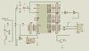
I am planning to make Port 1, Port 0 and Port 2.0-2.3 and Port 3.5 as the input and make the LED turn on by connecting the common on the input.
I hope someone can help me. I've attached an example of an input circuit to AT89S52.
Thank you!!
 

Attachments

  • at89s52.JPG
    at89s52.JPG
    40.1 KB · Views: 214
Normally for the transmisson You can use the USART of Your microcontroller.
When using a 4 wire RS485 Connection the transmitter and receiver of the RS485 Chip can be enabled fix.
When want to use only 2 wires the system only can work in half duplex mode and transmitter had to be switched off while receiving.
The LED can be switched on and off by an dedicated port of Your microcontroller, when receiving some proper signal by USART.
When less data on the signal in port the LED flickers so short, that no light can bee seen.
I would switch the LED on when one proper frame was received, and switched off after a short period of 40 to 100ms.

Your schematic looks like a isolated detection for a -24V signal.
An RS485 connection looks like this .
Normally there is no isolation between the bus subscribers.
You can use isolated RS485 Transceivers or use a own circuit to do this.

Here an example of microcontroller connection.

There are many usable chips for using as RS485 transceiver.
They differ about power consumption and maximum transfer rate.
MAX485, SN75176 ...
 
Last edited:
Normally for the transmisson You can use the USART of Your microcontroller.
When using a 4 wire RS485 Connection the transmitter and receiver of the RS485 Chip can be enabled fix.
When want to use only 2 wires the system only can work in half duplex mode and transmitter had to be switched off while receiving.
The LED can be switched on and off by an dedicated port of Your microcontroller, when receiving some proper signal by USART.
When less data on the signal in port the LED flickers so short, that no light can bee seen.
I would switch the LED on when one proper frame was received, and switched off after a short period of 40 to 100ms.

Your schematic looks like a isolated detection for a -24V signal.
An RS485 connection looks like this .
Normally there is no isolation between the bus subscribers.
You can use isolated RS485 Transceivers or use a own circuit to do this.

Here an example of microcontroller connection.

There are many usable chips for using as RS485 transceiver.
They differ about power consumption and maximum transfer rate.
MAX485, SN75176 ...

Thank you, I have put a MAX485 on the circuit although the one shown in the diagram is a MAX487 (since I can't find a library for a max485 component on proteus). Since I am a beginner at programming, although I know some basic C and assembly from the books, I can't figure out how to transfer data from ports serially to other microcontrollers. If my circuit is correct, is there any example codes on how to do it on C or on Assembly. Thank you so much for your response.
 

Attachments

  • at89s52.JPG
    at89s52.JPG
    67.1 KB · Views: 175
Just connect TXD to DI, RXD to RO, /RE to ground and another output pin on the MCU to DE.
Normally leave that control output low.

The default state is then that the signal from the balanced line bus is passed to the receive input of the MCU UART.

To transmit, wait for at least one character period with nothing received then set the control output high to enable the driver.
Send the data as a continuous burst, then set the control output low again.

You should get exactly the same data back in to the receiver, as you send it. If it does not match, possibly another device tried to send at the same time.

For simplicity in the software side, you should also add resistors to the bus to bias it so the RXD inputs are normally held high when the system is idle, so they do not get any false "start" bits.

eg. this is a typical bias & termination setup:
**broken link removed**

You only need the resistor network at one point if the cabling is not particularly long, or add it at the two extreme ends of the cable for long bus systems.
 
I've added resistors on the bus to bias of MAX485. The LED Turns on even without the microcontroller, and turns off when I put the -24 volts DC supply. I think that's what it's supposed to do, can you help me begin with the codes? I really don't know where to start on coding when it comes to UART or USART, or should I use embedded C or assembly? I've searched examples and codes all over the internet, but still can't find one or can't help me with this project. Thank you!
 
I guess You have a general problem.
The RS485 Chips are only to make the signal You want to sent compatible with the used Cable.

The serial signal had to be produced and received by the Microcontroller.

There are to set some registers of the USART to configure the bit rate, parity handling an the number of data bits.
( Take a look into the Datasheet Chapter USART Page 94).
After setting this, You can have to look into a specified register if the data buffer is empty.
If it is You can write a byte into the Data Register of the USART and it will be transmitted automaticly.
At 2 wire Connection the RS485 Chip has to be configured as transmitter by a additional Port befor sending.

Receiving works similar.
When a data byte was received a bit was set in an receive status register of USART and You can readout the USART Data Register then.
The better way is to use USART receiver interrupts and copy the received Bytes into buffer array.
But that's a little bit more complicated.

Basicly that works with any program language similar.

In some IDE's a function is preprogrammed to set the depending USART registers.
You only had to call that routine with the wished parameters and the USART Register will be wrote with the right values.

What IDE You wanna use?

I wanna suggest You to change to a little bit more modern controller like the ATMEGA 16.
For first experiments You can use the CodeVision AVR IDE then, that has a Automatic Programm Generator to avoid exactly Your register problem.
Be aware, the free version is Code resticted at 4k Sourcecode.
For later use You can use ATMEL ( now Microchip ) STUDIO 7.

I use CodeVision to configure the used Hardware and Copy the generated Code into Studio 7.
A few names and defines had to be changed, but in sum that works good and go fast.
 
Last edited:
I guess You have a general problem.
The RS485 Chips are only to make the signal You want to sent compatible with the used Cable.

The serial signal had to be produced and received by the Microcontroller.

There are to set some registers of the USART to configure the bit rate, parity handling an the number of data bits.
( Take a look into the Datasheet Chapter USART Page 94).
After setting this, You can have to look into a specified register if the data buffer is empty.
If it is You can write a byte into the Data Register of the USART and it will be transmitted automaticly.
At 2 wire Connection the RS485 Chip has to be configured as transmitter by a additional Port befor sending.

Receiving works similar.
When a data byte was received a bit was set in an receive status register of USART and You can readout the USART Data Register then.
The better way is to use USART receiver interrupts and copy the received Bytes into buffer array.
But that's a little bit more complicated.

Basicly that works with any program language similar.

In some IDE's a function is preprogrammed to set the depending USART registers.
You only had to call that routine with the wished parameters and the USART Register will be wrote with the right values.

What IDE You wanna use?

I wanna suggest You to change to a little bit more modern controller like the ATMEGA 16.
For first experiments You can use the CodeVision AVR IDE then, that has a Automatic Programm Generator to avoid exactly Your register problem.
Be aware, the free version is Code resticted at 4k Sourcecode.
For later use You can use ATMEL ( now Microchip ) STUDIO 7.

I use CodeVision to configure the used Hardware and Copy the generated Code into Studio 7.
A few names and defines had to be changed, but in sum that works good and go fast.

Right now i'm using Kiel Microvision to compile programs, while I use Arduino as ISP to dump program into the microcontroller through an ATmega2560.
What is the sequence of code i should do?
first: identify pins like the ports,
second: the type of transmission, modes and such
third: the loop that i want to program to do?

Thank you for the answers and recommendation, will look into those options as well.
 
The Ports You have to use are P3.0 ( RXD ) and P3.1 ( TXD ) of the Microcontroller.
I've never programmed an AT89Sxx microcontroller - sorry.

How to set the registers depends what Baudrate and transmission mode You want to have.
I've take a short look into datasheet.
When I'm understand that, the Baudrate is a fix divider of the microcontroller clock, or You have to use a timer to set this.
Bit order and parity handling is to set too.
To figure out what are the working values for You, is Your home work ;-)

Sending:
For sending I would do polling in Main loop.
Look into a status register of UART if the send buffer is empty, You can set the RS485 Chip as transmitter and write a byte into the UART data register.
When sending is done ( Data register is empty an no further Bytes to send ) reset the RS485 Chip as receiver again.

Receiving:
For receiving i guess an interupt driven one will work better.
For this I would declare a array as ring buffer. ( The size of that depends of the line speed and how many time the main loop takes for one round. )
Then define a write pointer and an read pointer and a flag to sign a received byte.

In the interrupt routine increase the write pointer and write the received Byte into the ring buffer.
Set the flag that a new Byte is arrived.

In Main loop look for this flag, when set increase the read buffer, readout the bytes and compute until the value of read buffer achiefes the value of write buffer.
Clear the receive flag.


That's only one possible solution to do this.
In Codevision that will work so ( Polling option is included too ).

Polling for receiving is possible too, but when the Main loop take to much time for a round Bytes can be lost.

Testing:
I like to use ASCII Characters for transmission protocol, because You can use a TTL Compatible Serial to USB adaptor to read the Data with a Computer and a terminal program ( terminal, terra term or any other ). But that is no must!
The additional advantige is You have defined line end characters ( Carriage Return, Line Feed ).
For testing the PC can also used as data transmitter to Your cicuit.
The TTL signal must connected with the TXD and or RXD Port of the AT89..
And it is better to remove the RS485 Chip when using the transmission line of the USB Adaptor.
 
Last edited:
So I tried to do it like this,
C:
#include<REG52.H>

void delay();

    sbit P1_0 = P1^0;
    sbit P1_1 = P1^1;
    sbit P1_2 = P1^2;
    sbit P1_3 = P1^3;
    sbit P1_4 = P1^4;
    sbit P1_5 = P1^5;
    sbit P1_6 = P1^6;
    sbit P1_7 = P1^7;
    unsigned char port1;

void main()
{
    TMOD=0X20;
    SCON=0X50;
    TH1=0XFD;
    TR1=1;
    delay();
    TI=0;
    SBUF=port1;
    while (TI==0);
    
    TI=0;
    delay();
    P2=0x00;
    while(1)
    {
    RI=0;
    while(RI==0);
    }
}
void delay()
{
 unsigned int x=60000;
 while (x--);
}

am I doing it right? sorry I just tried and edited what I read from the books.
 
Your Programm has no main loop.
Here is a exaple for an ATMEGA 16 Chip with full init and main loop.
C:
/*******************************************************
This program was created by the CodeWizardAVR V3.26
Automatic Program Generator
© Copyright 1998-2016 Pavel Haiduc, HP InfoTech s.r.l.
http://www.hpinfotech.com

Project : USART MEGA 16
Version : 0.0
Date    : 07.11.2017
Author  : Krug
Company :
Comments:
Test for RF01D


Chip type               : ATmega16
Program type            : Application
AVR Core Clock frequency: 8,000000 MHz
Memory model            : Small
External RAM size       : 0
Data Stack size         : 256
*******************************************************/

#include <io.h>

// Declare your global variables here

// Standard Input/Output functions
#include <stdio.h>
volatile unsigned char uc_timeout=0;
unsigned char datax[15];
unsigned char datapoint=0;

#define OVERFLOWTIME 15     //15 is about 0,5s

#define OVR 3

#define FRAMING_ERROR (1<<FE)
#define PARITY_ERROR (1<<UPE)
#define DATA_OVERRUN (1<<OVR)
#define DATA_REGISTER_EMPTY (1<<UDRE)
#define RX_COMPLETE (1<<RXC)

// USART Receiver buffer
#define RX_BUFFER_SIZE 32
char rx_buffer[RX_BUFFER_SIZE];

#if RX_BUFFER_SIZE<256
unsigned char rx_wr_index,rx_rd_index,rx_counter;
#else
unsigned int rx_wr_index,rx_rd_index,rx_counter;
#endif

// This flag is set on USART0 Receiver buffer overflow
bit rx_buffer_overflow;

// Timer 0 overflow interrupt service routine
interrupt [TIM0_OVF] void timer0_ovf_isr(void)
{
uc_timeout++;

}

// USART0 Receiver interrupt service routine
interrupt [USART_RXC] void usart_rx_isr(void)
{
char status,data;
status=UCSRA;
data=UDR;
if ((status & (FRAMING_ERROR | PARITY_ERROR | DATA_OVERRUN))==0)
   {
   rx_buffer[rx_wr_index]=data;
   if (++rx_wr_index == RX_BUFFER_SIZE) rx_wr_index=0;
   if (++rx_counter == RX_BUFFER_SIZE)
      {
      rx_counter=0;
      rx_buffer_overflow=1;
      };
   };
}

#ifndef _DEBUG_TERMINAL_IO_
// Get a character from the USART0 Receiver buffer
#define _ALTERNATE_GETCHAR_
#pragma used+
char getchar(void)
{
char data;
while (rx_counter==0);
data=rx_buffer[rx_rd_index];
if (++rx_rd_index == RX_BUFFER_SIZE) rx_rd_index=0;
#asm("cli")
--rx_counter;
#asm("sei")
return data;
}
#pragma used-
#endif

//This is the complete String readout for the reader
void makestring(void)
{
datax[datapoint]=getchar(); //Get the next character
datapoint++;
if ((datax[datapoint-2] == 0x13) && (datax[datapoint-1] == 0x10)) //End of string is reached?
    {
    datax[datapoint] = 0x00; //Insert the "C" String end
    puts(datax); //Any output routine could be insert here LCD, USART or something else.
    datapoint = 0; //Set Pointer to 0 for next card
    }
}


void main(void)
{
// Declare your local variables here

// Input/Output Ports initialization
// Port A initialization
// Function: Bit7=In Bit6=In Bit5=In Bit4=In Bit3=In Bit2=In Bit1=In Bit0=In
DDRA=(0<<DDA7) | (0<<DDA6) | (0<<DDA5) | (0<<DDA4) | (0<<DDA3) | (0<<DDA2) | (0<<DDA1) | (0<<DDA0);
// State: Bit7=T Bit6=T Bit5=T Bit4=T Bit3=T Bit2=T Bit1=T Bit0=T
PORTA=(0<<PORTA7) | (0<<PORTA6) | (0<<PORTA5) | (0<<PORTA4) | (0<<PORTA3) | (0<<PORTA2) | (0<<PORTA1) | (0<<PORTA0);

// Port B initialization
// Function: Bit7=In Bit6=In Bit5=In Bit4=In Bit3=In Bit2=In Bit1=In Bit0=In
DDRB=(0<<DDB7) | (0<<DDB6) | (0<<DDB5) | (0<<DDB4) | (0<<DDB3) | (0<<DDB2) | (0<<DDB1) | (0<<DDB0);
// State: Bit7=T Bit6=T Bit5=T Bit4=T Bit3=T Bit2=T Bit1=T Bit0=T
PORTB=(0<<PORTB7) | (0<<PORTB6) | (0<<PORTB5) | (0<<PORTB4) | (0<<PORTB3) | (0<<PORTB2) | (0<<PORTB1) | (0<<PORTB0);

// Port C initialization
// Function: Bit7=In Bit6=In Bit5=In Bit4=In Bit3=In Bit2=In Bit1=In Bit0=In
DDRC=(0<<DDC7) | (0<<DDC6) | (0<<DDC5) | (0<<DDC4) | (0<<DDC3) | (0<<DDC2) | (0<<DDC1) | (0<<DDC0);
// State: Bit7=T Bit6=T Bit5=T Bit4=T Bit3=T Bit2=T Bit1=T Bit0=T
PORTC=(0<<PORTC7) | (0<<PORTC6) | (0<<PORTC5) | (0<<PORTC4) | (0<<PORTC3) | (0<<PORTC2) | (0<<PORTC1) | (0<<PORTC0);

// Port D initialization
// Function: Bit7=In Bit6=In Bit5=In Bit4=In Bit3=In Bit2=In Bit1=In Bit0=In
DDRD=(0<<DDD7) | (0<<DDD6) | (0<<DDD5) | (0<<DDD4) | (0<<DDD3) | (0<<DDD2) | (0<<DDD1) | (0<<DDD0);
// State: Bit7=T Bit6=T Bit5=T Bit4=T Bit3=T Bit2=T Bit1=T Bit0=T
PORTD=(0<<PORTD7) | (0<<PORTD6) | (0<<PORTD5) | (0<<PORTD4) | (0<<PORTD3) | (0<<PORTD2) | (0<<PORTD1) | (0<<PORTD0);

// Timer/Counter 0 initialization
// Clock source: System Clock
// Clock value: 7,813 kHz
// Mode: Normal top=0xFF
// OC0 output: Disconnected
// Timer Period: 32,768 ms
TCCR0=(0<<WGM00) | (0<<COM01) | (0<<COM00) | (0<<WGM01) | (1<<CS02) | (0<<CS01) | (1<<CS00);
TCNT0=0x00;
OCR0=0x00;

// Timer/Counter 1 initialization
// Clock source: System Clock
// Clock value: Timer1 Stopped
// Mode: Normal top=0xFFFF
// OC1A output: Disconnected
// OC1B output: Disconnected
// Noise Canceler: Off
// Input Capture on Falling Edge
// Timer1 Overflow Interrupt: Off
// Input Capture Interrupt: Off
// Compare A Match Interrupt: Off
// Compare B Match Interrupt: Off
TCCR1A=(0<<COM1A1) | (0<<COM1A0) | (0<<COM1B1) | (0<<COM1B0) | (0<<WGM11) | (0<<WGM10);
TCCR1B=(0<<ICNC1) | (0<<ICES1) | (0<<WGM13) | (0<<WGM12) | (0<<CS12) | (0<<CS11) | (0<<CS10);
TCNT1H=0x00;
TCNT1L=0x00;
ICR1H=0x00;
ICR1L=0x00;
OCR1AH=0x00;
OCR1AL=0x00;
OCR1BH=0x00;
OCR1BL=0x00;

// Timer/Counter 2 initialization
// Clock source: System Clock
// Clock value: Timer2 Stopped
// Mode: Normal top=0xFF
// OC2 output: Disconnected
ASSR=0<<AS2;
TCCR2=(0<<PWM2) | (0<<COM21) | (0<<COM20) | (0<<CTC2) | (0<<CS22) | (0<<CS21) | (0<<CS20);
TCNT2=0x00;
OCR2=0x00;

// Timer(s)/Counter(s) Interrupt(s) initialization
TIMSK=(0<<OCIE2) | (0<<TOIE2) | (0<<TICIE1) | (0<<OCIE1A) | (0<<OCIE1B) | (0<<TOIE1) | (0<<OCIE0) | (1<<TOIE0);

// External Interrupt(s) initialization
// INT0: Off
// INT1: Off
// INT2: Off
MCUCR=(0<<ISC11) | (0<<ISC10) | (0<<ISC01) | (0<<ISC00);
MCUCSR=(0<<ISC2);

// USART initialization
// Communication Parameters: 8 Data, 1 Stop, No Parity
// USART Receiver: On
// USART Transmitter: On
// USART Mode: Asynchronous
// USART Baud Rate: 9600
UCSRA=(0<<RXC) | (0<<TXC) | (0<<UDRE) | (0<<FE) | (0<<DOR) | (0<<UPE) | (0<<U2X) | (0<<MPCM);
UCSRB=(1<<RXCIE) | (0<<TXCIE) | (0<<UDRIE) | (1<<RXEN) | (1<<TXEN) | (0<<UCSZ2) | (0<<RXB8) | (0<<TXB8);
UCSRC=(1<<URSEL) | (0<<UMSEL) | (0<<UPM1) | (0<<UPM0) | (0<<USBS) | (1<<UCSZ1) | (1<<UCSZ0) | (0<<UCPOL);
UBRRH=0x00;
UBRRL=0x33;

// Analog Comparator initialization
// Analog Comparator: Off
// The Analog Comparator's positive input is
// connected to the AIN0 pin
// The Analog Comparator's negative input is
// connected to the AIN1 pin
ACSR=(1<<ACD) | (0<<ACBG) | (0<<ACO) | (0<<ACI) | (0<<ACIE) | (0<<ACIC) | (0<<ACIS1) | (0<<ACIS0);
SFIOR=(0<<ACME);

// ADC initialization
// ADC disabled
ADCSRA=(0<<ADEN) | (0<<ADSC) | (0<<ADATE) | (0<<ADIF) | (0<<ADIE) | (0<<ADPS2) | (0<<ADPS1) | (0<<ADPS0);

// SPI initialization
// SPI disabled
SPCR=(0<<SPIE) | (0<<SPE) | (0<<DORD) | (0<<MSTR) | (0<<CPOL) | (0<<CPHA) | (0<<SPR1) | (0<<SPR0);

// TWI initialization
// TWI disabled
TWCR=(0<<TWEA) | (0<<TWSTA) | (0<<TWSTO) | (0<<TWEN) | (0<<TWIE);

// Globally enable interrupts
#asm("sei")

while (1)
      {
      while(rx_counter>0)
        {
        uc_timeout=0;   //Reset Timeout
        makestring();
        //Receive Data and generate a string
        }
      if(datapoint>0)   //Transmission in progress ?
        {
        if(uc_timeout>OVERFLOWTIME)  //Timeout overflown ?
            {
            uc_timeout=0;  //Yes! Reset Timeout
            datapoint=0;   //Reset data pointer
            }
        }
      else                 //Else waiting for new tag
        {
        uc_timeout=0;      //Reset Timeout
        }
      // Place your code here

      }
}

I tried to download the free version of the CodeVisionAVR and I can't find something for AT89S52.
Sorry, I'm really new to programming microcontrollers so I don't know which variables and loops that I am going to put in a code.
I am receiving a 5V in the port 1.0 of the microcontroller as well.

How can I put this into a code:
1.) Make the ports in at89s52 inputs while making the LED turn on whenever the -24 volts is received
2.)Make the data in ports be sent to SBUF for transmission to other microcontrollers.
3.)How can I make the other microcontrollers read it so they can show output the same as the transmitter's LED (e.g port 1.1 turns on, port 1.1 on receiver turns on as well)

I am really sorry for the troubles, I am really new at this and needed it to be done.

Thank you so much for you help!
 
I can't help thinking this is yet another college project, from a student who can't be bothered to do the work!.

I actually just graduated before the pandemic started, haven't landed a job and feels like a burden. Feels like **** while saying it here though.
and to be honest, actually this isn't a project.
So when someone asked me if I could fix this board, with the same schematics i've given, I said I'll try and take a look at it.
At first the transistor is burnt so I fixed it, thought that'll fix the board but it seems that the microcontroller's program has been corrupted so I tried to study programming microcontroller and I've been searching through the internet and reference books from my college days but to no avail thus I've been taken here when I searched "forums for microcontrollers".

So that's my story, sorry if it looks like I'm not working enough.
Thank you, everyone for the help though.
 
In a further Post I tryed to suggest You to use ATMEGA ( or ATtiny ) Chips.

I guess a ATMEGA8515 in Pin compatible to Your AT89C52, please check this out!

Some of the ATMEGA Series are used in different ARDUINO Boards.
CodeVision is possible then.
ATMEL Studio 7 supports this Chips.
BASCOM ( BASIC Compiler ) too.

The AT89 series is rather old.
I've only found the KEIL IDE to write source code for that ( I've not searched a long time ).

First You should try to get "C" Basics.
Nearly all microcontroller programs has a main loop.

EXAMPLE:
#include "controller"

volatile char a =3; // an char ( 8 Bit ) variable was defined that can be changed in interrups ( volatile ) too.
char b = 2; //A normal global variable was defined.

define tor 3 // At any place in sourcecode You put in the string "tor" the compiler put in the value 3 there

char readport (void)
{
return pina;
}

int main (void)
{
//init sequence
char i=0; //define a local variable named i
ddra = 0b00001111; //eg. lower nibble of port a is an output the word ddra would be defined in the controller include file and is an hex address

while(1)
{
//insert Your code here
i=readport(); // Function readport will be called and give back the value into variable i
}
}
This code will working for ATMEGA ( AVR Series ).

First step is to initialize the used hardware ( ports, spi, UART, timer, interrupts ).
At top of program code the #includes had to be done.
Normally there is a file that names the registers of Your used chip.
Other #includes must be done for memory declaration, complex math, or string handling, when You need that.
Further You had to declare the global variables
when this is done the main loop will be called and that runs ( when there is no bug or sleep function ) until the controller is powerd down.

Try to find some source codes for Your IDE and Chip and figure out how it works.
It's importent to find files for Your used IDE because C Code differs between Keil and other IDE's.

When You have more experience in BASIC Programming You can try to find a BASIC Compiler for the AT89 Series.
 
Last edited:
Status
Not open for further replies.

Latest threads

New Articles From Microcontroller Tips

Back
Top