Hello again! Fresh from another proejct, I am tasked with a new one...this time involving the venerable RS-485! Now, the network requires a bunch of devices, about 10 let's say, connected to a PC. THe devices will periodically send data to the PC. The PC, for the most part, only receives data, but can send commands as well to any devices. Looks like I have a transceiver-transceiver network here....
This is the first time I've tried my hands on this RS-485 thing, so I'll get the PIC-PC data sending correct first before trying to make everything tranceiving stuff. I'm using PIC18f4580 with SN75176 using modified codes from Jan Axelson's website.
I got one big problem so far. I've tested a working prototype board on Proteus, built one in real-life and tested the circuit. However, I'm using Hyperterminal on XP with no handshaking and the RTS pin from the serial port didn't go low after transmitting data. As such, it cannot receive any data from the PIC. I know the PIC did receive data and send back responses owing to the output LEDs but data isn't being received on the PC side(again, based on output LEDs and Hyperterm's own output).
I later made mods to the circuit, so that, on the PIC side, the pin that drives the SN75176's RE and DE high when transmitting data will also drive the SN75176's RE and DE on the PC side low to enable receiving. This in effect turns the line from two to three. It's wrong, but I'm just doing it to see how it'll really work if the RTS pin is working properly.
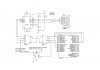
So how do I go on making the RTS pin working correctly? I know I can just create an app using Visual Studio to connect to the line and have RTS toggled manually, but doing so is too troublesome and I'd rather have a hardware solution if possible. Here I attached my circuit for better understanding.
This is the first time I've tried my hands on this RS-485 thing, so I'll get the PIC-PC data sending correct first before trying to make everything tranceiving stuff. I'm using PIC18f4580 with SN75176 using modified codes from Jan Axelson's website.
I got one big problem so far. I've tested a working prototype board on Proteus, built one in real-life and tested the circuit. However, I'm using Hyperterminal on XP with no handshaking and the RTS pin from the serial port didn't go low after transmitting data. As such, it cannot receive any data from the PIC. I know the PIC did receive data and send back responses owing to the output LEDs but data isn't being received on the PC side(again, based on output LEDs and Hyperterm's own output).
I later made mods to the circuit, so that, on the PIC side, the pin that drives the SN75176's RE and DE high when transmitting data will also drive the SN75176's RE and DE on the PC side low to enable receiving. This in effect turns the line from two to three. It's wrong, but I'm just doing it to see how it'll really work if the RTS pin is working properly.
So how do I go on making the RTS pin working correctly? I know I can just create an app using Visual Studio to connect to the line and have RTS toggled manually, but doing so is too troublesome and I'd rather have a hardware solution if possible. Here I attached my circuit for better understanding.