RODALCO
Well-Known Member
Hi Electrotech friends ,
To be honest I have two oscilloscopes at home anyway, but this is more of a challenge I am currently pondering about.
I have watched various YouTube video's of CRT TV's converted into simple oscilloscopes, or just music display devices, more like a bit of fun, and not for accuracy at all, and some results look pretty bad anyway.
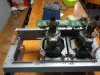
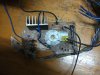
At the moment I am fiddling around with some 14" TV's (Magnetic Fields video) and learning as I go, as I have not too much knowledge how TV's work, but working daily with 11000, 22000 and 33000 Volts at a few hundred Amps in the Power board, and am careful with High Voltage protocol.
To run a normal CRT TV the horizontal coil needs to be in circuit as otherwise the TV shuts down. ( This has the high frequency scanning rate)
I have disconnected the vertical coil and via variac and transformer I can control the Vertical projection.
My idea is to drive a monochromatic RPTV Tube from the 14" TV flyback driver board, the Ultor Cap and HV focus etc. and control the deflection coils from an auxillary source.
The existing 14" TV deflection coils can be used as dummy ballast to keep the TV board working.
The way I look at it as long the coil impedance values are more or less the same it should work in principal.
I wonder if a monochromatic tube from a RPTV could be used.
I have three complete RPTV's at home all with the CRT's in it.
To make a monochromatic Red, or Blue or Green display would be cool.
Photo's and findings will be posted in due course.
Just not 100 % sure how to connect the tube up. Will attach a photo shortly.
To be honest I have two oscilloscopes at home anyway, but this is more of a challenge I am currently pondering about.
I have watched various YouTube video's of CRT TV's converted into simple oscilloscopes, or just music display devices, more like a bit of fun, and not for accuracy at all, and some results look pretty bad anyway.
At the moment I am fiddling around with some 14" TV's (Magnetic Fields video) and learning as I go, as I have not too much knowledge how TV's work, but working daily with 11000, 22000 and 33000 Volts at a few hundred Amps in the Power board, and am careful with High Voltage protocol.
To run a normal CRT TV the horizontal coil needs to be in circuit as otherwise the TV shuts down. ( This has the high frequency scanning rate)
I have disconnected the vertical coil and via variac and transformer I can control the Vertical projection.
My idea is to drive a monochromatic RPTV Tube from the 14" TV flyback driver board, the Ultor Cap and HV focus etc. and control the deflection coils from an auxillary source.
The existing 14" TV deflection coils can be used as dummy ballast to keep the TV board working.
The way I look at it as long the coil impedance values are more or less the same it should work in principal.
I wonder if a monochromatic tube from a RPTV could be used.
I have three complete RPTV's at home all with the CRT's in it.
To make a monochromatic Red, or Blue or Green display would be cool.
Photo's and findings will be posted in due course.
Just not 100 % sure how to connect the tube up. Will attach a photo shortly.