Continue to Site

Welcome to our site!

Electro Tech is an online community (with over 170,000 members) who enjoy talking about and building electronic circuits, projects and gadgets. To participate you need to register. Registration is free. Click here to register now.

  • Welcome to our site! Electro Tech is an online community (with over 170,000 members) who enjoy talking about and building electronic circuits, projects and gadgets. To participate you need to register. Registration is free. Click here to register now.

RPM Reader w/ Tachometer.. Help Required!

Status
Not open for further replies.

fireworks1

New Member
I am currently building a digital tachometer with a pulse generator/signal generator (correct me?!) that is to measure the RPM of a 12v DC Motor, that rotates a blade through a sensor and is able to generate a digital output (high - low) signal that will go to the digital tachometer.
It is for a school project and am having considerable problems with it.

I have been able to construct the digital tachometer, power supply and mount and house the 12VDC motor quite easily but its just the sig.gen that has gotten me into alot of problems.

When the digital tacho is connected up to the output of a commercial sig.gen, with the increase in frequency of the sig.gen comes an increased RPM reading on the digital tacho. When connected to the output of MY Sig.gen, the reading on the tacho lasts for a small time then comes up with no reading.

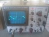
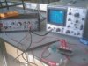
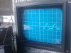
The problem exists in the IR LED - Phototransistor, opto-coupler subsystem. I have tried various changes with the subsystem but hve not yet been able to rectify the problem. When I connected my sig.gen to the Oscilloscope, it seems that there is a change in amplitude but no change in frequency of the output signal.

So what can I do??

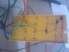
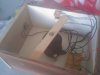
Also, some of these are various photo's taken throughout the journey. I intend to put a photointerrupter in tomorrow.

Help would be greatly appreciated.
 

Attachments

  • IMAGE_061.jpg
    IMAGE_061.jpg
    413.8 KB · Views: 437
  • IMAGE_062.jpg
    IMAGE_062.jpg
    417.8 KB · Views: 341
  • IMAGE_063.jpg
    IMAGE_063.jpg
    513.2 KB · Views: 350
  • IMAGE_058.jpg
    IMAGE_058.jpg
    608.4 KB · Views: 345
  • IMAGE_060.jpg
    IMAGE_060.jpg
    433.6 KB · Views: 244
  • IMAGE_059.jpg
    IMAGE_059.jpg
    511.7 KB · Views: 341
hi,
Is your local mains frequency 60Hz.???
 
50Hz. I live in Australia

hi,
Looking at the middle picture of the top row, its that the signal that dosnt change with the speed of the blade.?

It looks about 60Hz, could be 50Hz, if your scope is off cal.
 
hi,
Looking at the middle picture of the top row, its that the signal that dosnt change with the speed of the blade.?

It looks about 60Hz, could be 50Hz, if your scope is off cal.

Yes, that is the current signal that does not change frequency and the
calibration is probably out. Old equipment...
 
Yes, that is the current signal that does not change frequency and the
calibration is probably out. Old equipment...

My best guess its mains pick up...:)

If you cover the IR receiver/detector, block out the light completely, does that signal disappear.???

Set the scope to 'dc', lets see the true signal level.
 
My best guess its mains pick up...:)

If you cover the IR receiver/detector, block out the light completely, does that signal disappear.???

Set the scope to 'dc', lets see the true signal level.

Ill do this all tomorrow. Anything else you suggest I should
test or take photos of for you to help rectify the problem?
 
Ill do this all tomorrow. Anything else you suggest I should
test or take photos of for you to help rectify the problem?

I would like to help you sort it out.:)

I see on your pics a photodetector, how is it wired, do you have a circuit diagram to post?
 
I would like to help you sort it out.:)

I see on your pics a photodetector, how is it wired, do you have a circuit diagram to post?

Thanks very much.
My teacher is a qualified Electrical engineer who retired from working
power stations so he hasn't really got a great deal of knowledge in the
electronics sector so your help is genuinely appreciated.

I have a phototransistor - IR LED opto-couple wired up in parallel so
to speak, in series with resistors. I have a horrible circuit drawing so
I'll try download a schematics program to help create a schematic.

I am putting this in tomorrow to test with:
**broken link removed**

Worth doing?
 
Thanks very much.
My teacher is a qualified Electrical engineer who retired from working
power stations so he hasn't really got a great deal of knowledge in the
electronics sector so your help is genuinely appreciated.

I have a phototransistor - IR LED opto-couple wired up in parallel so
to speak, in series with resistors. I have a horrible circuit drawing so
I'll try download a schematics program to help create a schematic.

I am putting this in tomorrow to test with:


Worth doing?

With that opto interrupter do you have enough safe clearance for the fan blades.???

If you have a simple reverse biassed photodiode connected to a +V supply via resistor that could be a problem.

If the anode of the photodiode is at 0V and the cathode is to the resistor, the signal will be weak and there will be a 'dc' offset.

I'll wait for your drawing of the opto detector circuit.:)
 
Last edited:
What is the RPM of the motor? maybe it is to fast for response time of your sensor?
 
What is the RPM of the motor? maybe it is to fast for response time of your sensor?

That's what I am trying to measure with the digital tacho...
I am really struggling with ideas on what to change now.
It could be rotating too fast at higher RPM's but even
when it is slower, there is no reading on the digital tachometer.
 
That's what I am trying to measure with the digital tacho...
I am really struggling with ideas on what to change now.
It could be rotating too fast at higher RPM's but even
when it is slower, there is no reading on the digital tachometer.

hi,
Looking at the video I dont see any change in the pulse rate as you adjust the fan speed.

Again I will ask, PLEASE post a circuit diagram of the opto circuit, emitter and receiver.:)
 
Last edited:
hi,
Looking at the video I dont see any change in the pulse rate as you adjust the fan speed.

Again I will ask, PLEASE post a circuit diagram of the opto circuit, emitter and receiver.:)

Ohh that.
Couldn't find a program to create it on the computer so
I will just draw it at a latter time.
 
Ohh that.
Couldn't find a program to create it on the computer so
I will just draw it at a latter time.

Ok. put on the drawing as much detail as required so that we can understand the circuit.:)
If your PC has a scanner, you could scan a hand drawn circuit.
 
If you have the Jaycar photo interrupter then I would try,

Connect the emitter of the photo transistor to ground.
Connect a 2.2k resistor from (pt) collector to 5V.
Connect a 1k (just in case) resistor from (pt) collector to pic pin.
Connect the LED to either 5V or 12V with a resistor to limit the current to 30mA.

Let us know how it goes.

Edit, from the data sheet. How do you know which pin is which?

Mike.
 
Last edited:
If you have the Jaycar photo interrupter then I would try,

Connect the emitter of the photo transistor to ground.
Connect a 2.2k resistor from (pt) collector to 5V.
Connect a 1k (just in case) resistor from (pt) collector to pic pin.
Connect the LED to either 5V or 12V with a resistor to limit the current to 30mA.

Let us know how it goes.

Edit, from the data sheet. How do you know which pin is which?

Mike.

Thanks heaps Mike but I'm going to be honest with you, what do you
mean by Pic pin? Also as you are aware, not the best data sheet.
When you receive the component however, the legs are the different
length and so I connected the collector to the positive rail and the emitter
to the negative... Is this correct?

I am starting to concede defeat :(
 
Status
Not open for further replies.

Latest threads

New Articles From Microcontroller Tips

Back
Top