Hi all, this is my first post, so please let me know if it's not kosher or if I should move it elsewhere. I would like to share my summer project with you, including the open hardware design files. I would also like to get your suggestions for further improvements on this project.
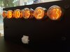
Yes, yes, I know it's just another nixie clock, but I'm really enjoying having it in house so far. Here's a few quick pictures of the clock as it is now:


The PIR sensor is used to shut off the tubes when no motion is detected (to preserve the lifetime of the nixie tubes). The nixie tubes are driven by separate BCD decoders which are in turn driven from the RPI's GPIO pins. I've programmed the clock to alternate between the current time, current external temperature (using openweathermap API) and internal temperature, and current AQI (air quality index, using AirNow API). I implemented the AQI screen because of the fire and smoke situation that we currently have in California, and it's been very handy to look at before going on walks or runs outside. The whole project was programmed in Python for simplicity.

Block Diagram

The board I designed is a rectangular 230mm x 75mm board with a 40 pin (standard 2.54mm pitch header) connector for connecting up to a Raspberry Pi and with footprints for all the parts in the above block diagram. The enclosure is a laser-cut design which can be made in a variety of materials (I chose a cheaper black acrylic material). The schematic and layout were done in KiCAD and the enclosure was designed in FreeCAD. All these files are provided in the repository below.
Design Files Repository
Bitbucket Repository
I've written about and continue to write about this project on my blog. You can find the landing page for that project **broken link removed**. You can find more posts there as well (including **broken link removed**) as the PDFs for the schematic and pcb layers (also on the bitbucket repository).
Future Improvements
There's a few things I'd like to add to this project going forward:
Yes, yes, I know it's just another nixie clock, but I'm really enjoying having it in house so far. Here's a few quick pictures of the clock as it is now:
The PIR sensor is used to shut off the tubes when no motion is detected (to preserve the lifetime of the nixie tubes). The nixie tubes are driven by separate BCD decoders which are in turn driven from the RPI's GPIO pins. I've programmed the clock to alternate between the current time, current external temperature (using openweathermap API) and internal temperature, and current AQI (air quality index, using AirNow API). I implemented the AQI screen because of the fire and smoke situation that we currently have in California, and it's been very handy to look at before going on walks or runs outside. The whole project was programmed in Python for simplicity.
Block Diagram
The board I designed is a rectangular 230mm x 75mm board with a 40 pin (standard 2.54mm pitch header) connector for connecting up to a Raspberry Pi and with footprints for all the parts in the above block diagram. The enclosure is a laser-cut design which can be made in a variety of materials (I chose a cheaper black acrylic material). The schematic and layout were done in KiCAD and the enclosure was designed in FreeCAD. All these files are provided in the repository below.
Design Files Repository
Bitbucket Repository
I've written about and continue to write about this project on my blog. You can find the landing page for that project **broken link removed**. You can find more posts there as well (including **broken link removed**) as the PDFs for the schematic and pcb layers (also on the bitbucket repository).
Future Improvements
There's a few things I'd like to add to this project going forward:
- Improve the nixie footprints by rotating them clockwise slightly and make all of the holes significantly larger; this should allow the person soldering the tubes to rotate them in position and then solder them.
- Move the power supply onto the main board
- Remove the 40pin ribbon cable and allow a RPi Zero W to be directly connected instead (via a 90 degree header).
- Clean up and fix a few things on the PCB
- Try out multiplexing the tubes; if this looks good, I’ll do so on the final clock to reduce the number of necessary IOs. That will allow me to add a SPI/I2C temperature sensor to put on the board for a better sense of the room temperature (rather than using a fixed offset from the die temp of the Broadcom processor on the RPi board).
")
