Continue to Site

Welcome to our site!

Electro Tech is an online community (with over 170,000 members) who enjoy talking about and building electronic circuits, projects and gadgets. To participate you need to register. Registration is free. Click here to register now.

  • Welcome to our site! Electro Tech is an online community (with over 170,000 members) who enjoy talking about and building electronic circuits, projects and gadgets. To participate you need to register. Registration is free. Click here to register now.

Right channel distortion on vintage fisher rs-2010

Status
Not open for further replies.

suzook

New Member
I have a vintage fisher rs-2010 that uses the "famous" stk packs. I get sound on both channels, but the rt channel has some distortion. My dc offset on good channel is 7mv, and the distorted channel is 32mv. That shouldn't cause my issues. Any idea where to start? Thanks
 
OK, think I found my issue. Q13 which feeds bad channel, has only .01v, should have .3, and q15 has same value. So Im thinking voltage is too low causing distortion. Thoughts? so change q13, q15? or something else?
So i have a short across b and e on q13, q15. This is with it in circuit. The matching pair of q14.q16 on good channel no short. Could q13, and q15 be bad?
 
Can you post the Q09 & Q11 waveforms from both channels? Also, what is the voltage between those two points with the amp idle? (for each channel).

Q13 and Q15 are part of the protection circuit. They are used to sense the voltage across the power stage output resistors (R51 & R53) and limit the drive to the STK is the current is too high.

They should read 220 Ohms between emitter and base while in circuit and unpowered, due to the base-emitter resistors?


Check the R51 & R53 output resistors are reading under one ohm and inspect the solder joints, make sure there are no cracks or dry joints?

If those are OK, you could remove or lift one end of D07 and D09, to isolate the protection part from the STX input drive. Just keep the volume very low to avoid any possibility of overloading the amp whilst unprotected.

Then check the collectors of Q09 & Q11 again & see if the output distortion has gone when checking with the scope?

It's certainly not impossible both transistors have failed, though it seems a bit of a coincidence. If it's OK with those diodes disconnected I'd definitely replace Q13 &Q15, and reconnect the diodes.

[Use the part number equivalents in the faulty channel if I'm looking at the wrong one ?]
Q13 and 15 read a short across b and e, in circuit.So scope on q9, 11?? How? Sorry, I'm very new with this, and a scope. Thanks
 
Last edited:
Can you post the Q09 & Q11 waveforms from both channels? Also, what is the voltage between those two points with the amp idle? (for each channel).

Q13 and Q15 are part of the protection circuit. They are used to sense the voltage across the power stage output resistors (R51 & R53) and limit the drive to the STK is the current is too high.

They should read 220 Ohms between emitter and base while in circuit and unpowered, due to the base-emitter resistors?


Check the R51 & R53 output resistors are reading under one ohm and inspect the solder joints, make sure there are no cracks or dry joints?

If those are OK, you could remove or lift one end of D07 and D09, to isolate the protection part from the STX input drive. Just keep the volume very low to avoid any possibility of overloading the amp whilst unprotected.

Then check the collectors of Q09 & Q11 again & see if the output distortion has gone when checking with the scope?

It's certainly not impossible both transistors have failed, though it seems a bit of a coincidence. If it's OK with those diodes disconnected I'd definitely replace Q13 &Q15, and reconnect the diodes.

[Use the part number equivalents in the faulty channel if I'm looking at the wrong one ?]
d07,d09 lifted, still have bad output on speaker out on that channel.
 
Last edited:
Can you post the Q09 & Q11 waveforms from both channels? Also, what is the voltage between those two points with the amp idle? (for each channel).

Q13 and Q15 are part of the protection circuit. They are used to sense the voltage across the power stage output resistors (R51 & R53) and limit the drive to the STK is the current is too high.

They should read 220 Ohms between emitter and base while in circuit and unpowered, due to the base-emitter resistors?


Check the R51 & R53 output resistors are reading under one ohm and inspect the solder joints, make sure there are no cracks or dry joints?

If those are OK, you could remove or lift one end of D07 and D09, to isolate the protection part from the STX input drive. Just keep the volume very low to avoid any possibility of overloading the amp whilst unprotected.

Then check the collectors of Q09 & Q11 again & see if the output distortion has gone when checking with the scope?
q9, q11 still have an odd waveform compared to q10,q12 on clean channel, with the diodes lifted. Where is this signal going bad. GRRRR
 
So scope on q9, 11?? How? Sorry, I'm very new with this, and a scope.
The two yellow junctions I marked on the diagram, earlier - you say you are seeing different waveform there between the two channels; can you post photos of the waveforms you see, for all four points?

Also please measure (DC voltage) between those two point, in each amp channel, with power on but no signal?
Thanks. Still trying to figure out this scope. It's an analog tek 2235. I have to change the v and ms when measuring anything besides the speaker output. It's definitely challenging for me
 
The two yellow junctions I marked on the diagram, earlier - you say you are seeing different waveform there between the two channels; can you post photos of the waveforms you see, for all four points?

Also please measure (DC voltage) between those two point, in each amp channel, with power on but no signal?

Soldered everything back in. I'm thinking my scope trigger is whacked, or its me. I adjust it, get wave out of speaker outputs. When i test inside, it varies, and i have to change volts div, and sec div. Not sure if that's how it should work. I have some voltages for you, those are easy.
Q9, B53.8 C1.1 E53.3
Q10, same as Q9
Q11 B-54.8 C-1.1 E-55.4
Q12 same as Q11
Here is where things get interesting...
Q13 B.01 C1.01 E 14mv
Q14 B.30 C1.09 E 33mv
So Q13 is way lower than Q14, which is close to what it should be according to Swrvice Manual.
Q15 B.01 C-1.01 E14mv
Q16 B.24 C_1.09 E33mv
So same thing with Q15 being lower than should be. SO both Q13, Q15 are not putting proper voltage. So What does this mean? Hopefully someone can figure it out.
More testing...Q13, Q15, test short across B and E. There is NO short across B and E on Q12,Q14. This would explain the wrong voltages, NO? New Q13,Q15 seems the next logical stop? Q12, andq14 look clean, like the top wave in pic, q13,q15 is the bad wave in pic. Signal is clean though on q9, q11.
 

Attachments

  • 20220806_162321.jpg
    20220806_162321.jpg
    703.1 KB · Views: 177
Last edited:
Soldered everything back in.
Whilst the D07 & D07 were out, Q13 & 15 could not cause a problem; leave the diodes out and forget them for now - the problem is to the left of those, in the circuit.

You have not given the voltage measured directly between the two yellow points for each channel; that is critical.

Leave the scope set for AC coupling and it should work on the same setting for speaker or the yellow points.

Post photos of the waveform on the yellow points, both channels?

You could also check that you have around 0.6-0.7V between base and emitter in all the transistors to the left of the STK in the circuit?
Sorry. As I said, I'm lost. I forgot those other voltages. So voltage from d07 to d09???one leg on each? 2.15 volts across. And I don't understand to the left. the left on the schematic?? That ac setting helped big time with the scope. I just assumed to use dc. So i narrowed down the bad signal to R37. Its bad on one side, not clean. Thats where I get the ugly wave. I don't think that tells anything though. LOL.
 
Last edited:
So voltage from d07 to d09???one leg on each? 2.15 volts across. And I don't understand to the left. the left on the schematic??
The diodes should still be disconnected, so between the junction of Q09 collector to the STK and Q11 collector to the STK.

Looking as the schematic diagram, the audio signal flow is left-to-right, input to output.


The protection circuit (Q13 / Q15 and the components connected to their bases etc.) works right to left, but as long as those two diodes are disconnected that is isolated and should be ignored, as the problem is still there without it.

Q13 & Q15 need attention eventually, but are not the cause of the distortion, if the problem remains with D07 and D09 disconnected - so leave the diodes out and forget that part until after the main fault is found. Just keep the volume down until we get back to that & fix it.


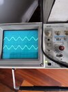
If you see the distorted waveform on the at some point and the input signal is good, then the fault is either at the point you are looking at, or nearer the amp input; to the left, in the schematic.


The yellow points I marked are critical points - the transition from normal, easily replaceable components to the STK0105 hybrid. If the fault is before those (in the Q09 / Q11 circuits or nearer the input / left), it's easily fixable - otherwise the STK needs replacing.

That is why I want the voltage between those points and the waveforms at them.
 
Ok, will remove diodes and retest. I'm wondering if it's just easier to swap out the stk with a spare? I'm a bit busy rest of week. I will update when I get a chance. Thanks for all the help, and explanation. It's definitely a learning process.
 
So new stk, and replace q13,q15???
Yep, that sounds about right.

It may have had a severe overload on that channel somehow, enough to destroy the protection transistors & then take out the STK module?? Or the transistors went by chance and the module had no protection.
 
Unit is alive again! Put 2 stk 0105's in. Sounds really nice. Anyone know how to measure wattage output with a scope? Here's a pic of it in action.
 

Attachments

  • 20220805_082706.jpg
    20220805_082706.jpg
    2.9 MB · Views: 173
Unit is alive again! Put 2 stk 0105's in. Sounds really nice. Anyone know how to measure wattage output with a scope? Here's a pic of it in action.
Extremely simply - it's very, very easy.

Just input a 1KHz sinewave, with the volume turned right down, and put an 8 ohm load (of sufficient wattage) on the output.

Apply the scope across the load resistor, and turn the volume up until the scope trace just starts to clip, then back it off to just before clipping - measure the peak to peak value of the trace. Do this quickly, and immediately turn it back down once completed.

Divide that value by 2.828 (to convert to RMS), square it, then divide by 8.

However, be aware that a full power test like this is stressful for the amplifier, and there's a chance it could die.

There's also little point in doing a power test like this on a repaired amplifier, just play music through it and make sure it sounds loud and good quality.
 
Thanks for the instructions. Only reason I wanted to test it, was see what the aftermarket 0105's put out. But I guess your right. What's the difference? It sounds great, and i will never be playing at full power.
 
Thanks for the instructions. Only reason I wanted to test it, was see what the aftermarket 0105's put out. But I guess your right. What's the difference? It sounds great, and i will never be playing at full power.
You need to consider how the amplifier (and pretty well all other transistor amps) works - the output power is essentially dependent on the supply rails - NOT on the output devices. If the output devices aren't capable - they will overheat and die.

It's simple to estimate the output power with just a multimeter - just measure the supply rails, knock a few volts off for losses, and use that figure in the calculations above. Basically the p-p output can't exceed the supply rails, so the maximum p-p output will be a few volts less.
 
Status
Not open for further replies.

Latest threads

New Articles From Microcontroller Tips

Back
Top