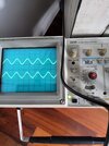
What frequency are you putting in?, and it's still unclear what the scope is set to, as you can't see the line on the knob in the picture.
Set the gain control to 50mV, set the probe to x10, and make sure the Red 'Cal' control is fully clockwise (it should almost always be there, and may have a click position), this gives 500mV per division on the scope. Then adjust the volume for 2 squares on the scope, giving 1V p-p.
The chances of a relay causing distortion is extremely low, but you can certainly check both sides of the contacts if you wish.
If you're getting the same signal on the power board?, where on the power board? - as it's only on one channel it can't really be on the power board.