I have a plan to add variable accent/mood lighting to rooms using high powered LEDs, such as the 1W or 3W Luxeon stars
I want to have a way to select any color (probably 128 colors or something like that), and then adjust brightness once the color is selected. I plan on doing this via a PWMing program on an ATMega microcontroller, because that's what I have.
I can use the program to change the PWM for whatever features I want to add.
I'm not worried about the input methods and software so much as I am the interface with the LEDs.
I want to have a series string of a few LEDs of each color, with 3 PWM channels, each controlling one color.
Obviously, the uC cant source enough current to power these LEDs (350mA-1A per channel), so I need to interface. I think the IRL540N (datasheet pdf) would work, as its threshold voltage is only 2V, and seems to be used fairly often for logic level interfacing. I wish to PWM at around 100Hz. The uC should be able to source about 25mA, and I was wondering if this would be enough to drive the FET at that frequency.
The datasheet says the total gate charge is listed as 74 nC, and the input capacitance is listed as 1800 pF (I assume this means if the input is the Gate). Not sure which of these I would go about using to calculate the charge time for the gate when sourced by 25mA of current. Can someone explain this?
In addition to my drive problems, are Red LEDs inherently brighter or dimmer than blue or green LEDs? i.e. if I have 3 LEDs of each color, will one color be brighter at the same current level? I can either compensate by having different numbers of LEDs for each color or by adjusting the amount of pulse width that each channel gets. if anyone has experience with brightness levels that would help. it seems that blue LEDs "look" brighter than red ones...
Also, red, blue, and green LEDs all have different forward drops. I could just use a resistor to deal with this, but that seems inefficient, as I will need some fairly hefty resistors (at least 1W.) Does anyone know of a more efficient way to run the LEDs (perhaps an LM317 current regulator?)
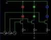
A basic schematic is attached, with current limiting resistors just as place holders. (I had to use a really basic online editor for this one; the circles are LEDs. It counts the fwd voltage on all the LEDs as the same, but thats how I plan to use the MOSFETs; the square wave sources stand for the PWM outputs of the uC.
I want to have a way to select any color (probably 128 colors or something like that), and then adjust brightness once the color is selected. I plan on doing this via a PWMing program on an ATMega microcontroller, because that's what I have.
I can use the program to change the PWM for whatever features I want to add.
I'm not worried about the input methods and software so much as I am the interface with the LEDs.
I want to have a series string of a few LEDs of each color, with 3 PWM channels, each controlling one color.
Obviously, the uC cant source enough current to power these LEDs (350mA-1A per channel), so I need to interface. I think the IRL540N (datasheet pdf) would work, as its threshold voltage is only 2V, and seems to be used fairly often for logic level interfacing. I wish to PWM at around 100Hz. The uC should be able to source about 25mA, and I was wondering if this would be enough to drive the FET at that frequency.
The datasheet says the total gate charge is listed as 74 nC, and the input capacitance is listed as 1800 pF (I assume this means if the input is the Gate). Not sure which of these I would go about using to calculate the charge time for the gate when sourced by 25mA of current. Can someone explain this?
In addition to my drive problems, are Red LEDs inherently brighter or dimmer than blue or green LEDs? i.e. if I have 3 LEDs of each color, will one color be brighter at the same current level? I can either compensate by having different numbers of LEDs for each color or by adjusting the amount of pulse width that each channel gets. if anyone has experience with brightness levels that would help. it seems that blue LEDs "look" brighter than red ones...
Also, red, blue, and green LEDs all have different forward drops. I could just use a resistor to deal with this, but that seems inefficient, as I will need some fairly hefty resistors (at least 1W.) Does anyone know of a more efficient way to run the LEDs (perhaps an LM317 current regulator?)
A basic schematic is attached, with current limiting resistors just as place holders. (I had to use a really basic online editor for this one; the circles are LEDs. It counts the fwd voltage on all the LEDs as the same, but thats how I plan to use the MOSFETs; the square wave sources stand for the PWM outputs of the uC.