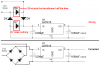
Having a bridge rectifier in a package does not prevent one from connecting it incorrectly. If it is connected the way you drew it, you will have a half wave rectifier (and possibly a burned out diode), which could be the source of your hum.
Is the transformer rated at 18V RMS?
Are you able to measure the DC voltage at the input to the regulator?
Do you have an oscilloscope?
If so, observe the input and the output of the regulator, and tell us, or post a picture, of what you see.