Continue to Site

Welcome to our site!

Electro Tech is an online community (with over 170,000 members) who enjoy talking about and building electronic circuits, projects and gadgets. To participate you need to register. Registration is free. Click here to register now.

  • Welcome to our site! Electro Tech is an online community (with over 170,000 members) who enjoy talking about and building electronic circuits, projects and gadgets. To participate you need to register. Registration is free. Click here to register now.

Resistors and?

Status
Not open for further replies.

Electronman

New Member
Hello,

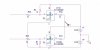
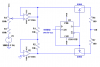
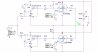
The below picture is part of my design.
I regularly need to change the values of R1 and R2 in real circuit till get the best response of the circuit, but the values of those resistors must be the same at any time. I thought of using a doubled volume but after testing one of them with my ohm meter I noticed that the values do not change similarly (I had 3k for one while 500ohms for the other at a fixed arm point!).
Can everybody help me with a good and reasonable solution please?
I have to replace the resistors with a variable resistor till I get a good response from the circuit and then I'll use 2 fixed resistors for the final circuit, but for now I have to use something to change those values at the same time.
Thanks.
 

Attachments

  • ss.JPG
    ss.JPG
    45.3 KB · Views: 354
You used a dual gang pot and the resistances were not the same on both gangs? Get a new pot. They might be off slightly, but only by a few ohms, not 100s or more.
 
The TLC4066 is an ordinary CD4066 that is made by many companies.
With a 12V supply its switching resistance is typically 30 ohms but could be as high as 90 ohms.
Each IC has 4 switches and in one IC their resistance matches within typically 5 ohms or 15 ohms max.

It will be much better if the 1k resistor values are higher. Try 10k ohms.
 
Actually both switchers in the above picture are symmetrical (both receive the input signals and generate an output signal which is symmetrical). I have used those two resistors (I.e R1 & R2) to give the input of the above switcher a positive DC offset and th bellow one a negative DC offset, so both must have similar values.
I have used a TL072 Op-amp to cause the input signals to be symmetrical (the circuitry is as an inverting op-amp and the other is an noninverting one). then I inject both outputs of the the op-amp into the inputs of both switchers.
The control pins of both switchers have a symmytrical frequency which is much higher than the input frequency and is generated by a 4069 chip.
Now you can notice that the values of R1 and R2 have to be exactly the same to have a completely symmetrical signal in the output of the switcher chip.
 
The TLC4066 is an ordinary CD4066 that is made by many companies.
With a 12V supply its switching resistance is typically 30 ohms but could be as high as 90 ohms.
Each IC has 4 switches and in one IC their resistance matches within typically 5 ohms or 15 ohms max.

It will be much better if the 1k resistor values are higher. Try 10k ohms.

Well, if I use the higher resistance resistors then the DC offset would be reduced.

How did you notice that I should use the higher resistors?
 
Last edited:
you can buy ganged pots that sre not of the same value, I once bought a double pot that was 1 and 100 Kohms, i expect that they were intended as a voltage divider of a voltage divider allowing main and fine adjustments in a circuit
 
As the datasheet for the 4066 says, its switch resistances in one IC match fairly well but are not exactly the same. If your 1k resistors are changed to 10k then the error in the switch resistances is 1/10th of the total and if 100k resistors are used then the error is 1/100th.
 
Ok, Here is the whole circuit (except of the 4069 oscillator and two 78xx regulators which I used them to generate a dual supply) and the related output waveforms:
I guess it has several deficiencies yet so want to improve it as much as I can, please put your ideas here.
 

Attachments

  • sm2.JPG
    sm2.JPG
    221 KB · Views: 222
  • sm3.JPG
    sm3.JPG
    127.8 KB · Views: 194
  • sm.JPG
    sm.JPG
    88.4 KB · Views: 227
Last edited:
I made an AM modulator and a suppressed-carrier single-sideband modulator/demodulator with an MC1496 IC.

The TL07x and TL08x opamps have the problem called, "Phase Inversion" when an input voltage gets to within 3V or 4V from the negative supply voltage. It will occur with your non-inverting opamp. The output suddenly inverts.
 

Attachments

  • opamp phase inversion.PNG
    opamp phase inversion.PNG
    15.3 KB · Views: 218
I made an AM modulator and a suppressed-carrier single-sideband modulator/demodulator with an MC1496 IC.

The TL07x and TL08x opamps have the problem called, "Phase Inversion" when an input voltage gets to within 3V or 4V from the negative supply voltage. It will occur with your non-inverting opamp. The output suddenly inverts.

Oh, I did not know of that problem!
Thanks audioguru for your notice, you are a genius!

How to solve the said problem? What about using LF356N or LF411CN?

I noticed a problem at the output of the real circuit (i.e. at the output of the switchers while they are operating), I do not know what you call it but I have regular unwanted quakes in the output, like when a circuit suffers voltage leakage to operate (It is analogous to your voice quake at a very cold place lol).
my guess lead me to think of L7812CV and L7806CV regulators that are used in series to give a dual voltage (+12V, ground and -12V) while the whole circuits consumes almost 600MA. the 7806 gets warmer than 7812. Yes I do know that those regulators are able to give more than 1A but it was a guess.
The problem can be due to the duty cycle of 4069 oscillator too.
As you know I have to invert the control freq for one of switchers too. The 4069 oscillatr is doing so for me too. I guess it is not able to generate 50% of duty cycle.
So for now I have a duty cycle equal to 44% for one switcher and 56% for the other one. please consider that every switcher generates half of the modulated signal. What you think of not having a symmetrical control (carrier) signal?

I have to say that now I am thinking maybe the said problem (quakes) is due to the last problem you mentioned too?

Unfortunately I don't have signal generator to find the main reason of the said problem.
 
You have a 7812 positive regulator but you do not have a negative regulator.
The 7806 makes a very poor "ground" because it pulls up but does not pull down.

I use the MC3407x opamps that are fast, have inputs that work at the negative supply voltage and have a minimum supply voltage of 3V. They are a "super" LM358 or LM324 but do not have their high crossover distortion and low speed. They do not have the phase inversion problem.

here's the circuitry of the regulators that I used to make a split power supply.
So it is not a good circuitry? So it is better to go for a positive/negative regulator like the second pic, right?
I will follow to get those MC families, but don't you have any idea for LF356N and LF411CN.

I have heard of MC1496, but it is a very old chip. I found 4066 more flexible than that nasty chip but do not know if my final product will be better than using that chip or not?
 

Attachments

  • d.JPG
    d.JPG
    4.4 KB · Views: 219
  • und.JPG
    und.JPG
    4 KB · Views: 187
Last edited:
It appears that you are trying to control a 4066 connected to +6V and -6V, but one control signal swings from 0 to +5V, and the other swings from 0 to -5V. The top switch will go from "half" on to full on. The bottom one will go from "half" on to full off. Is that your intent? I don't think so. To fully switch, the control input needs to swing essentially rail to rail.
To do a proper job of offset, sum it into the summing node of the inverting amp, and invert that output with the other op amp to give you the other switch input. You might need rail-to-rail output op amps to do this.
 
Last edited:
Ok thanks master!
I'll try the second circuit which is based upon positive and negative regulator chips,
Is it so matter if I use 7812 and 7912 from 2 different company?
Hope I can solve the problem by doing so.

I think I need a bit help in accordance with what I told about duty cycle too
 
Last edited:
It appears that you are trying to control a 4066 connected to +6V and -6V, but one control signal swings from 0 to +5V, and the other swings from 0 to -5V. The top switch will go from "half" on to full on. The bottom one will go from "half" on to full off. Is that your intent? I don't think so. To fully switch, the control input needs to swing essentially rail to rail.
To do a proper job of offset, sum it into the summing node of the inverting amp, and invert that output with the other op amp to give you the other switch input. You might need rail-to-rail output op amps to do this.

I have used a 4069 chip as an oscillator for control pins. I have grounded the negative pin of 4069 to the ground of my supply (the output of 7806) (you can see it as 7812 one regulators pics but its because I found those pics through the net and could not edit them because they are too small in size lol)

Hey man your direction for making a rail to rail oscillator worked in Spice.
It does work in real circuit too, but the result seem to be similar to the before circuit (see the below pic).

Well I though of putting a resistor across the inverting input of the op-amp and the negative pin of the supply, do you know what I say? But it did not work properly with the first circuitry. I will try it again with rail to rail control signals too.
I want to ignore using a dual power supply and use just a single ended one. I want to use a voltage divider for the inputs of the op-amp. What's your idea?
But due to my input signal(i.e 3kHz) I guess I have to use a dual supply because one wire in the input has to be grounded too? Maybe it does work if put in negative pin too?

P.s. I do not understand of going from "half" on to full off and vice versa for a Switch?!
 

Attachments

  • n.JPG
    n.JPG
    90.3 KB · Views: 331
  • n1.JPG
    n1.JPG
    225.3 KB · Views: 206
  • n2.JPG
    n2.JPG
    132.7 KB · Views: 201
Electronman, I think I misunderstood your previous schematic. I thought your control signals were square waves, with the low level being 0 and the high levels being +5 for one of the controls and -5 for the other. i now understand that they are sine waves, 10V p-p, and 180 degrees out of phase. My bad.:(
However, they still need to be square waves that go from -6V to +6V, or at least -5V to +5V.

The comment about the switch being half off (or on) was due to my misunderstanding about your control signals, which I thought were at zero volts for half of each cycle.
 
Last edited:
Electronman, I think I misunderstood your previous schematic. I thought your control signals were square waves, with the low level being 0 and the high levels being +5 for one of the controls and -5 for the other. i now understand that they are sine waves, 10V p-p, and 180 degrees out of phase. My bad.:(
However, they still need to be square waves that go from -6V to +6V, or at least -5V to +5V.

The comment about the switch being half off (or on) was due to my misunderstanding about your control signals, which I thought were at zero volts for half of each cycle.

As I told I use a 4069 buffer inverter to generate a 80kHz freq for both control pins of two switchers, so yes I use square wave for control pins. An RC circuit connected to 4069 generates that oscillating freq and then I connect one of outputs of the 4069 into one of its inputs to achieve both positive and negative 80 kHz signals.
Now my desire is 50% of duty cycle for those positive and negative signals, how can I achieve that? I think the best solution is using a CMOS divider but with consideration of the oscillating freq (i.e. 80 kHz) I am in doubt which chip is able to create the said duty cycle?? Any idea please?

By the way, I converted the whole circuit so that it works with a single ended power supply (I used just one 7812 chip), and made a voltage divider by two 1k resistors for the non inverting pins of the op-amp and the modulating input.
Please help me more to improve the circuit.
 
Last edited:
You can generate 160kHz and then divide by two with a CD4013 configured as a toggle (divide-by-two) flip-flop. Then you can use the Q and ~Q outputs to drive your 4066s.
Below is a way you can adjust the modulation index with only one pot.
You can use any op amp that has rail-to-rail inputs and output and can handle at least 12V vcc-vee.
 

Attachments

  • amplitude modulator.PNG
    amplitude modulator.PNG
    15.8 KB · Views: 281
Last edited:
Thanks Ron,
I do like your modification, it tells that you are a real engineer.
I was thinking of 4013 and 4027 before but was not sure if they are able to work down to 80kHz because I read somewhere that those chips are good for times less than 5 micro seconds!
I have converted the real circuit so that it works with single ended power supply, So hope your configuration does work just with voltage divider resistors too.
 
Status
Not open for further replies.

Latest threads

New Articles From Microcontroller Tips

Back
Top