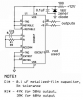
A CD4047 IC has an RC oscillator and a divide-by-two digital divider giving a perfect 50:50 duty-cycle. A second divided output is inverted from the other output.
Then the CD4047 IC will replace your CD4069 oscillator and the CD4013 divider.
The timing resistor for the CD4047 oscillator should be at least 10k ohms.
Then the CD4047 IC will replace your CD4069 oscillator and the CD4013 divider.
The timing resistor for the CD4047 oscillator should be at least 10k ohms.