Continue to Site

Welcome to our site!

Electro Tech is an online community (with over 170,000 members) who enjoy talking about and building electronic circuits, projects and gadgets. To participate you need to register. Registration is free. Click here to register now.

  • Welcome to our site! Electro Tech is an online community (with over 170,000 members) who enjoy talking about and building electronic circuits, projects and gadgets. To participate you need to register. Registration is free. Click here to register now.

Replacing an NPN for a PNP in the following circuit?

Status
Not open for further replies.

Delinquent

New Member
Hi all, looking for a bit of urgent help!

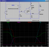
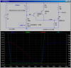
I found the following schematic on the net:

**broken link removed**

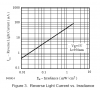
The pot should IMO have the take off at the wiper not both ends, but regardless, other than that this does exactly what I want... erm... almost! The problem is the layout of the circuit. I want to use the circuit (or produce the same end result) with a pre-existing sensor lead I have. This is a 3.5mm stereo jack wired to a IR transmitter and receiver, wired thus:

**broken link removed**[/IMG]

Which I cannot modify as it works with a different device as well, which I need to incorporate this circuit into.

Reading and researching, I think I can replace the NPN 2n2222 with a PNP 2n2907a and then just move the pot between base and ground, with the output from the IR rx then going in to the base between base and +ve?

But... that is all based on my total knowledge of transistors (and pretty much electronics completely!) being learned today, off the net, in breaks between work!

Could anyone revise the above schematic for me so that my above sensor can just plug in before I destroy any more components with the soldering iron?!!
 
Last edited:
Something is very wrong with your sensor schematic. If LED1 is really the photo-emitter, then it needs to be forward biased, Likely, this is a photo-interrupter, so the detector is an NPN photo-transistor?
 
LOL well that should show you just how adept I am at electronics! You are completely correct, I have indeed stuck the LED in the wrong way around on the schematic - I was in a real rush when I drew it, but that's just my excuse for ineptitude!

In the real sensor, it is indeed the correct way round. LED1 is an 'Infrared emitter 5mm TSUS5400' and the received is a 'BPW41 High Speed PIN Photodiode' that is spectrally matched.
 
Ok, the attached is right off the BPW41 datasheet. Note that at nominal illumination levels, the current through the diode will be ~10uA.

So your task is to trigger an SCR when the current goes above 10uA? or goes below 10uA?

What is the gate triggering current for your SCR?
 

Attachments

  • BPW41.png
    BPW41.png
    19.4 KB · Views: 232
basically when the lighting is cut off, trigger the SCR (it's to photograph something passing through the beam) There are other circuits available but I'm told this is very good at detecting small fast objects hence sticking with it!

Gate trigger current of the SCR is 200uA - it's an X00619 if that helps
 
Here 'tis. I'm assuming that when illuminated, the BPW41 puts out 15uA; 2uA due to the ambient light while the beam is blocked. You should confirm that using a 5V supply and a uAmeter connected in series with the detector.
 

Attachments

  • DF159.png
    DF159.png
    35 KB · Views: 226
Sir, you are a star, many thanks!

Can I be a complete pain and ask a further couple of questions on that - firstly, what would need to be changed if it were a 9v supply? (I ask because I have a whole host of equipment that will be running at the same time from a 9v supply...)

secondly, would it be possible to swap a variable resistor in at either R1 or R2 to make sensitivity adjustable? I'm told this is highly beneficial!
 
Here it is:
 

Attachments

  • DF159a.png
    DF159a.png
    37.5 KB · Views: 207
thank you so much, very much appreciated! I shall get some bits ordered first thing in the morning and start getting a PCB assembled!

Now all I have to do is work out why nothing else on this whole project works quite as it was supposed to!!
 
Mike, can I be a complete pain again please?! Would it be possible to add an LED into that circuit, that would show when the beam was NOT broken? So it would be lit only when the sensors were in alignment?
 
Last edited:
Mike, shouldn't you add a gate current limiting resistor?

R6 does it. Because of the resistor in the emitter, the Darlington acts as a constant current source.
 
Mike, I couldn't get a couple of parts - closest fit were a 470k pot and for the scr a x00619, bit having no joy getting it working. Do you think just those two components are ok in your circuit? I tried adding a simple led with a thyristor to show when there was input from the pt, but not even that lit!
 
Do you have a DMM that has an input impedance > 10MegΩ in the DC Volts mode? If so, measure the voltage at the node named "det" in the circuit (wrt ground) while putting/removing an object in the light path. Report back with the two voltages.
 
Thanks Mike. With object in path voltage was 0.94v, with the path clear it's 1.85v.

That means that very little energy from the photo-emitter is reaching the photo-detector. What is the emitter? How hard are you driving it? What is the distance from the emitter to the detector? What kind of ambient lighting?
 
The emitter is a TSUS5400, which was suggested by the vendor as spectrally matched to the detector. Distance that that measurement was taken at was very small, only about 2 inches at most!!! Ambient light was 3 low energy lightbulb, each equivalent to 60w

For a full picture, the sensor rig (wired as per the diagram on prev page) is two 3ft lengths of a medium quality speaker cable, one end is a 3.5mm stereo jack. The 470o resistor is at the emitter end of the cable, the two +ve's are joined at the stereo jack.

The funny thing is, I have had problems with pretty much every circuit I've tried off the internet, I've made lots of sensors up in the past with different lengths and qualities of wire, different emitters and detectors... I ended up finding a simple detector circuit on the net and made up a simple dedicated unit to test the leads involving a thyristor a 220 ohm resistor and an LED. All the leads I have, tested, work well on the unit. All the sensors I've made light the LED (albeit dimly) at a distance of about 2ft, but as soon as I plug it into a trigger circuit it seems to drop to a matter of an inch or so!
 
Last edited:
You did try to "align" the optical axis of the emitter with that of the detector?
Try it while watching the voltmeter as above.
 
indeed, I checked all that when originally making the leads up and consequently when I've run into problems, it was what prompted me to make the little test unit. The rx has quite a wide viewing angle and testing it with a mm showed the axis makes little difference at close range.
 
Status
Not open for further replies.

Latest threads

New Articles From Microcontroller Tips

Back
Top