Continue to Site

Welcome to our site!

Electro Tech is an online community (with over 170,000 members) who enjoy talking about and building electronic circuits, projects and gadgets. To participate you need to register. Registration is free. Click here to register now.

  • Welcome to our site! Electro Tech is an online community (with over 170,000 members) who enjoy talking about and building electronic circuits, projects and gadgets. To participate you need to register. Registration is free. Click here to register now.

Repairing a BWD 521 cathode ray Oscilloscope - no traces, hissing noise

Status
Not open for further replies.
atferrari, I'll take a stab in the dark....
Heat?
Or the screws were tightened too much or unevenly during assembly?
Or some weird magnetic effect from the coils - stretching a long bow there I guess... :)
 
Yes, thats what I thought, and in the first picture it looks quite discoloured.
Given the age though, if I can get the scope working, I'll replace a lot of the caps.
 
Hi joshAU,
Have you removed the top of the transformer core before taking the pictures or was there no top part of the core fitted originally ? I have never seen an EHT transformer with an open magnetic path.

Les.
 
Hi joshAU,
Have you removed the top of the transformer core before taking the pictures or was there no top part of the core fitted originally ? I have never seen an EHT transformer with an open magnetic path.

Les.
Just what I was thinking- the bolts look like they should hold down the second half of the core. As Jim said the core is cracked too, so not much inductance. No wonder the 2n3055 is getting hot.

The good news is that if the transformer is shot it would not be a big deal to make a new one.

spec
 
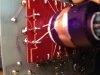
Thought I'd test the transformer first...
Just to be sure I removed the cable you had me test earlier that bypassed C75 and C81.
I still haven't put those components back in yet, as I don't think they'd affect these measurements.

OK.
I measured the resistance from the lower side of R116 to the lower side of R115, as per the schematic, which should be correct to measure the resistance of the 31 turn coil, and it shows no resistance.

I measured the resistance from the right hand side of R117 to the the lower side of R114, to measure the 15 turn coil, and it also shows no resistance.

I measured the resistance from the top of the secondary coil - at the +50 point, to the left hand side of D17 and it measures 641 Ohms.
hmm...

I measured the resistance from the right of R119 to the left of R120, and I get 18 Ohms.
hmm again. ;)

Hopefully the method I used was correct.
Feel free to let me know if that is not the case. :)
Josh
That all sounds good Josh
 
I just realised then JimB that it was some type of ferrite.
So it shouldn't be part of the problem then I guess.
I will take your recomendation re gluing it though, once I've worked out the problem.
Thanks again, I appreciate it.
Josh

Josh when you glue the crack in the core make sure it is well ligned up and clamped absolutely close together while the glue sets. If you dont do that you wont get the enough inductance. Wrapping adhesive tape around the core leg is the best way to do the clamping.

The more I look at that transformer the more I think there is a bar of ferrite missing from the top. One thing you could try is to get a hunk of ferrite from another source and tape it across the exposed faces of the transformer. Make sure it contacts the entire exposed ends of the U shaped core.

spec
 
Last edited:
Hi joshAU,
Here is a method to see if the inverter is oscillating.
Diode probe.jpg


Make up this circuit and connect it to your multimeter set to a DC range. (I would suggest the 200 volt range to start with.) Connect the test leads from this circuit one to the collector of the 2N3055 and the other to the positive of C73. If it is oscillating I would expect to see a reading of between about 20 and 80 volts. If it is not oscillating there will be no reading. None of the components are critical. the capacitor can be between 0.01 uF and 1.0 uF (Do not use an electrolytic capacitor.) Any of the 1N400x series diodes (Or even a 1N4148) will do. Any resistor between 10K and 100K will do.

Les.
 
Have you removed the top of the transformer core before taking the pictures or was there no top part of the core fitted originally ? I have never seen an EHT transformer with an open magnetic path.
Yes I noticed that and assumed that the transformer had been dismantled intentionally by joshAU.
There definitely should be a bar of ferrite across the top, held down by nuts on the two screwed rods.
Notice the two white (ish) dots on the ends of the bottom half of the core, paper spacers to give a slight gap to limit the coil inductance.

If that ferrite is missing, there will be very little EHT and the 2N3055 will get steaming hot.

JimB
 
wow...quite a few responses, and sorry, I had to go and do some more renovations on the bathroom.
No rest for the wicked...

Thanks for all the information given, and good morning spec. :)

Les Jones, and spec , the EHT board with the transformer was originally enclosed in a metal casing, which, now you mention it, I just had a look inside and saw another ferrite looking device attached to the top of it.
I thought it was just some sort of earth shielding box, and didn't even notice the ferrite thingaboby attached underneath...my bad... :(, so I proceeded assuming it wasn't really required for testing...
Assumptions hey...
I guess I really should have posted a few pictures with my original posts - it may have helped.

So... where too from here I guess is my next question?

Should I glue the cracked bit, then reattach the top as it was originally, and obviously put back the q42 transistor, the diode and 2x caps I removed from earlier testing, and test it, or do you guys think there is still something else causing the problem?

I'm a bit confused, just in case you guys hadn't already picked that up. :)
 
oops, I missed a couple of posts there...

Les Jones, thank you for the info on how to test if the inverter is oscillating. I should be able to figure that out, thank you.

And JimB, yes, I had dismantled the transformer, albeit unknowingly, thinking I was just removing the EHT board from its housing, so I could test the components, not realising that I had actually removed the top of the transformer at the same time.
 
Ah, all is revealed!

Yes, glue the broken bits back together.
Remove the ferrite bar from the cover and fit it carefully on the top of the transformer.
Ensure it is held down firmly, do not over tighten the nuts, That is maybe what broke the core in the first place.
Carry on fault finding.

JimB
 
good morning spec. :)

Good afternoon Josh- just had a nice Sunday roast. It is 2:45pm now in the UK :happy:

the EHT board with the transformer was originally enclosed in a metal casing, which, now you mention it, I just had a look inside and saw another ferrite looking device attached to the top of it.

Thank god that there is a reason for the missing link in the magnetic circuit. I just could not see how the oscillator could have ever worked as shown in the pictures. That missing piece of ferro material is the equivalent of cutting a wire in an electrical circuit.

What might have happened is that the bottom of the core got cracked some time. That in itself would not do much, but if the gap widened, as it may well do when it is all bolted together, that would decrease the inductance radically. It will also change the operation of the oscillator. The gap in the core is like putting a high resistance in an electrical circuit.

The crack in the core is not that important in itself. What is important is how well the faces of the crack mate when you do the repair. So, as I said before, don't just rely on glue, but also wrap tape around the core to hold the two pieces together firmly and in line. Once that is done you should make sure that the bridge piece is also mating well and I would also put some tape around that, so that the transformer is a stand-alone item. It is remotely possible that, once the transformer core is fixed, the oscillator will start up, but don't hold your breath. :wideyed:

spec
 
Last edited:
Hi again.
Sorry spec... I still haven't got the time zones worked out.

Thanks all for the advice, and sorry, I should have posted pictures from the beginning.
Like I said, I'm no expert. ;)

OK, I'll try gluing the crack as neatly as possible, and put it back together and see what happens.
Fingers crossed, but yes spec, I won't hold my breath.

I'm at work now so I can't post any pictures of the top of the core.
Its actually attached to the top of the metal casing that the EHT board sits inside of, so I have to push the two threads coming from the top of the transformer through the holes in the top ferrite, and through the holes in the top of the housing.
I'm not sure if I can remove the top of the transformer from that housing - there are no screws or anything holding it in place from memory, so I'm guessing its glued in place.
So, I'll try gluing the crack, following the above suggestions, then replace the components I removed, then install it into the housing and tighten up the screws carefully and retest it.

In regards to gluing it... rather than using superglue, would it be better to not actually put any glue into the edges of the gap itself, but clamp it together and then glue it on the outsides of the crack with something like araldite?
I might be able to reduce the gap more that way than by applying superglue to the internal of the crack, or will such a thin layer of superglue not matter?

Thanks again.
 
Hy Josh,

Oh I see about your problem with the ferrite bar retention. A thin layer of superglue will be fine providing that you can clamp the two halfs of the core together while the superglue is still in the thin state. I don't want to cross what JimB said, but epoxy would be better because it takes much longer to set and would give you more time. I have never used superglue on ferrite, so I cant really comment on how well it works on ferrite, but I have used epoxy many times.

A very thin layer of adhesive of any type will not affect the magnetic circuit too much. As an aside, some transformer cores have an air gap fitted by design. It is a bit like putting a higher value resistor into an electrical circuit. It reduces the inductance and makes it less likely that the core will saturate.

Just thinking out loud now: It would be a great help in fault finding if you could assemble the transformer without the can on. Can I suggest that you make a metal bar to go over the ferrite bar or is the ferrite bar stuck solid to the metal can. There is an adage in engineering that any item, never mind how simple, which cannot be seen/accessed, will always give problems.:eek:

spec

PS; are you saying tat the PCB is mounted in the metal can?
 
Last edited:
OK.
Well, I had a look at how the top of the tranformer was attached... a bit of double sided tape, so yes, @ spec, I can now assemble it outside of the can.
The top of the transformer core appears to have some sort of pcb like board on top of it, I'm guessing to insulate it from the casing, that has two holes drilled through it for the bolts to go through, so I should be able to glue it, then put the top on, and tighten it up, outside of the box.
I got some superglue, and some araldite - epoxy resin stuff, which I use pretty regularly fixing broken hinge mounts etc.
So I'll superglue the crack itself, then reinforce the outside of it with epoxy.
That should do the trick.

I like that adage by the way. :)
Perfect for this situation too.
I'll report back soon.
 
Josh, I would use Areldite in the crack too. It is a well used approach.

spec
 
OK, so I'm now typing with my toes, as I've somehow glued the transformer to my left hand, and, in the process of removing it, I've also glued my right hand to the front panel controls on the scope.
So, apologies for any typos that may follow.

Alright, no, I didn't. :)
I didn't get a chance last night, so will have to try again tonight.
 
OK, sorry for the delay.
I resoldered the components I removed earlier so the circuit is back to how it was.
Checked there was no new smoke or other changes. All good - same as before, Q42 still overheating, etc.

I've glued the crack in the ferrite, but I will leave it overnight to cure fully before I put the top back on and test it.
I'll report back ASAP.
 
So I couldn't wait... and knowing epoxy, I decided an hour or two was more than enough.
I carefully reassembled it with the top of the transformer in place and powered on, but no joy.
Exactly the same as before, no trace and the 2N3055 still gets hot rapidly.
So I guess that wasn't the main fault, but still good to repair anyway.

While gluing the cracked ferrite, I noticed on thing that MAY be the problem...
On the primary (purple) coil windings, I noticed what looked like a couple of bits of wire sticking out from the base of the winding.
They are very fine wires, finer than any of the other wires...
I guess I'll need a photo to show it properly.
Could this be the culprit?
I suspect so... but I'm so overly confused by this whole saga that at this stage I can't tell.
Sorry I didn't report it earlier... I had checked over it previously looking for anything obvious, but I suspect the lighting at my desk wasn't good enough for my eyes to spot it before.
It was only when I noticed the crack and went to fix it that I bought in a lamp to shine a light on things.

SO... moving on.
I've included two photos that hopefully show what I'm talking about, however its really hard to focus in so close.
I've circled the wires on the photos that appear to come out from underneath the purple shielding, and then just stop, hanging in mid air...
No scorch marks or other signs or a short.

Again, I'm a bit confused, as I have little experience with transformers..
On the entire brown/amber board that I assume has the primary coil/s above it, it has 12 connections going around it to connect wires to.
Going on the first photo IMG_2662b.JPG, I'll number them from top right anticlockwise, so the top row would be pins 1-5, then down the left hand side would be pins 6-8, then on the bottom row would be pins 9-12.
However, going by the circuit diagram, only 6 of these would be used, and it does appear that is the case for some of the pins... ie, pines 1 to 4 seems to be of a very fine wire with lumps/beads in it, pin 5 has a even finer wire, the same apparent diameter of the shorted wires.
Pin 6 seems disconnected, then 7&8 have a larger wire, probably twice the diameter of the first two types of wire.
then, going along the bottom, pins 9-12 are all the same type of large wire, although the centre two, pins 10 & 11, are doubled up, and I assume they are all the same wire.
A check with the multimeter shows zero resistance between them, so yes...
Pins 1 to 4 do not seem to be directly connected... ie the resistance seems to increase from pin 1 to pin 2 (4 Ohms) to pin 1 to pin 3 (6.5 Ohms) to pin 1 to pin 4 ( 9 Ohms)
Pin 5 is a bit of a mystery...its the same diameter cable as the burnt/broken wires, and there doesnt appear to be another pin that has the same diameter wire... except for pin 6, which has no wire going to it, but also doesnt seem to connect to the mainboard below it. Pin 5 is directly connected to C80 positive side.
Pins 1-3 don't connect to anything on the mainboard directly
Pin 4 connects to the left hand side of R120
Pin 5 is directly connected to C80 positive side.
Pin 6 connects to the right of R112
Pin 7 connects to C71
Pin 9 connects to C74
Pin 10& 11 just loopback
Pin 12 connects to C73....

Sorry to throw all this out there...
I'll try to step back and breathe a lot and try to make sense of it.

I guess I'm confused though, as the circuit diagram only mentions 8 total points connecting from the pcb to the transformer, two on the secondary apparently and the rest, at least physically, on the primary board.
So there is the beaded wire... then the thicker wire, then the really thick wire... two of each, ie 6 wires... then add the 2 wires from the secondary, that should be all the wires.
So what the hell are these even finer wires doing there... and what is their purpose.... sigh....
I'm confused, just in case you didn't know already.
 

Attachments

  • IMG_2662B.jpg
    IMG_2662B.jpg
    1.2 MB · Views: 325
  • IMG_2664B.jpg
    IMG_2664B.jpg
    731.9 KB · Views: 319
Status
Not open for further replies.

Latest threads

New Articles From Microcontroller Tips

Back
Top