Continue to Site

Welcome to our site!

Electro Tech is an online community (with over 170,000 members) who enjoy talking about and building electronic circuits, projects and gadgets. To participate you need to register. Registration is free. Click here to register now.

  • Welcome to our site! Electro Tech is an online community (with over 170,000 members) who enjoy talking about and building electronic circuits, projects and gadgets. To participate you need to register. Registration is free. Click here to register now.

Repair a KRK 10s Subwoofer - parts id

Status
Not open for further replies.
If it matches R494, then ok.

I tried cleaning off the corrosion and that wasn't exactly a good thing..
I can see the blue, grey, and black, but the rest not so great...

Here's the pic:

blue2.jpg

So... I thought to myself, why don't I just try to get a reading on it and on the Auto Ohm setting I consistently got 69.8, 69.6, 69.7.
LCD on the VM said M ohm, so I think we're good.

I measured the green one as well at it showd 1.031.

What do you think?

Thanks!
 
That's a gold stripe thanks. And the green does show to be a 1k, and 31 Ohm more, not a prob with that.

As for the blue resistor, that stripe looks to be gold, thus 68 Ohm range.

Also in cases here :Edit, I allays mean here as in here at my home area: the Diode test function on some resistors have helped clear to the absolute values, as the diode test on many meters are not usually loss, meaning that the Diode test usually reads low values on Ohm to low K Ohm ranges as it depends on the tool used. Again thanks for the reading. However the Diode test is usual only for preference, as that's what gets stated when I ask why use that range to any that I have seen use that range for testing resistors. (I think they do that so they don't have to continuously switching from Ohm to diode test and in some cases may show if transistors are ok in some odd fashion whilst still on the board). (for the meters that can read high diode ranges).
 
Last edited:
That's a gold stripe thanks. And the green does show to be a 1k, and 31 Ohm more, not a prob with that.

As for the blue resistor, that stripe looks to be gold, thus 68 Ohm range.

Also in cases here the Diode test function on some resistors have helped clear to the absolute values, as the diode test on many meters are not usually loss, meaning that the Diode test usually reads low values on Ohm to low K Ohm ranges as it depends on the tool used. Again thanks for the reading.

Glad I've got it right. Once I get all the parts in had I'm going to take my time re-assembling, soldering, fixing whatever tracks need it, etc..
Because of the assembly being tight once everything is together, I'm most likely not going to test levels across the boards when it's hot.

BackPanel.jpg

I'd rather do whatever isolated measurements of the board, get it assembled, and closed in the box, and flip it on.
Also, the guy who was helping me "Spec" earlier had me put a big resistor across the speaker terminals for protection.
I may not bother with that either.
 
If you go with that method, may want to use a power strip with an on off switch, all tho, even if the power cord is switched off, the caps can hold enough power co cause problems if something else is affected, however there is really no way around this without testing methods that involve at least a scope of some kind and test leads all over the place. The resistor should not be to unusual to add in at the speaker, close back with a few screws, power in then test, any strange buzzing or hum, remove the power, also may want to watch the speaker on power on, if it goes one way in or out of the cone and hangs there, then something is latched on the driver control. Not likely but a possibility. If any issues result, then a prompt power removal is advised. If things work well, then the resistor can be removed. Current lock through a speaker is low, it just doesn't take much to damage them. Have some Pioneer procomps here rated at 1000W RMS that went up when an amp decided to latch on the push stage due to the ceramic resistor exploding. The fet went latch ballistic as they need removal of signal power when supposed to be off, the low current volt flow to the device had no where to go and the shut down rating of the device was not properly met.
 
Overall the positive voltage met the negative in brief moments, I would use the term for, an engine roaring round a race track, then hearing the term a rod let go.
 
If you go with that method, may want to use a power strip with an on off switch, all tho, even if the power cord is switched off, the caps can hold enough power co cause problems if something else is affected, however there is really no way around this without testing methods that involve at least a scope of some kind and test leads all over the place. The resistor should not be to unusual to add in at the speaker, close back with a few screws, power in then test, any strange buzzing or hum, remove the power, also may want to watch the speaker on power on, if it goes one way in or out of the cone and hangs there, then something is latched on the driver control. Not likely but a possibility. If any issues result, then a prompt power removal is advised. If things work well, then the resistor can be removed. Current lock through a speaker is low, it just doesn't take much to damage them. Have some Pioneer procomps here rated at 1000W RMS that went up when an amp decided to latch on the push stage due to the ceramic resistor exploding. The fet went latch ballistic as they need removal of signal power when supposed to be off, the low current volt flow to the device had no where to go and the shut down rating of the device was not properly met.

Thanks for the advice and insights.. I supposed I could get the resistor in series (didn't finish that task) at the spkr terminals, assemble, test, and if all seems good
I could disassemble and clip off the resistors (I made the leads long so I could remove without desoldering..

The last time I had it powered up, there appeared to be no power problems (I could play the main powered speakers thru the sub fine) but we'll see right?
 
Right, One thing is certain, a major difference without the device in close reach to directly see and diagnose any problems based on process of elimination, and any companies that do not release any data or documents other than how to use a working model can make things difficult, Besides stating the obvious.

Also the Panasonic by the datasheet states pin 1 Emitter, pin 2 Collector, and pin 3 Base. It carries the same pin out as the 3206 that was removed.
 
Interesting question regarding the new Pan Transistor - Don't hurry and feel you need to respond fast.
I can put this Pan Transistor in last.

When looking at the data sheet for the Panasonic Transistor:

https://media.digikey.com/pdf/Data Sheets/Panasonic Semiconductors ICs PDFs/2SC1473(A).pdf

It's either misleading or wrong in terms of what side the Base is on because in the bottom section where it shows the half circle shape it indicates with the round side facing me that base (3) is on the right. Even though I heard that the flat side with writing on it usually indicates left to right.

diagram.png

I was just testing the new parts, and realized I didn't want to install the Base on the wrong side.

I did a test with the flat side facing me (side with writing on it), and put the positive lead on the right (Base), and put the negative lead on the collector and emitters, and got a reading for both...

Collector + Base = .596
Emitter + Base = .612

The other way around with the round side facing me the same test showed no reading.

What do you think?
 
The reading states correct for NPN type pin 3 as the Base. An image just to give an example, with the letters facing person.
 

Attachments

  • The Leads.png
    The Leads.png
    917.3 KB · Views: 275
Side note, on quite a majority of BJT type transistors, the Collector reads the lower value vs the Emitter. Base set point of the transistor for the N channel leads the Collector into operation, thus shorter path of Base to collector (less resistance), the Diode path to emitter results the higher reading (more resistance). P channel also, however the values on PNP type are usually closer in being near equal readings from the base as the set point. Overall transistors based on type and design can vary.
 
The reading states correct for NPN type pin 3 as the Base. An image just to give an example, with the letters facing person.

Awesome, thanks for the validation. I was aware and thankful of the indicators printed on the board. Just a misleading diagram (lol).
 
That is correct. But strictly speaking (sorry for pun) the resistor should go in the high side- if there is one (some amps have a bridge output so there is no high side).

Yes, that is correct. You can forget about the speaker now that you have protected it and tested it. Yes, we will be working on the power amplifier board mainly.

Bear in mind that mains voltages will be present on the circuit up to the primary of the toroid transformer (big & round) so please take care.

The next test is to set your meter to DC volts and measure the voltage across the speaker terminals. (it should be 0V to +-0.1V).

spec

Hi Spec,

Quick question.. I'm not sure what "go in the high side" means. No rush as I'm waiting for a delivery of white grease before I re-assemble
everything.

Thanks!
 
Hi Spec,

Quick question.. I'm not sure what "go in the high side" means. No rush as I'm waiting for a delivery of white grease before I re-assemble
everything.

Thanks!

Hi CJ,

In a normal audio power amplifier, the amplifier output connects to one terminal of the loudspeaker (the high side), and the other terminal of the loudspeaker connects to 0V (also called ground, earth, or chassis). It makes no difference which side the resistor connects: it will protect the speaker equally well. But from a technical, purist, point of view it is best to connect the protection resistor in series with the high side of the speaker.

spec
 
Last edited:
Hi CJ,

In a normal audio power amplifier, the amplifier output connects to one terminal of the loudspeaker (the high side), and the other terminal of the loudspeaker connects to 0V (also called ground, earth, or chassis). It makes no difference which side the resistor connects: it will protect the speaker equally well. But from a technical, purist, point of view it is best to connect the protection resistor in series with the high side of the speaker.

spec

Excellent, thank you! Now I understand... Not being in this space so much I hadn't heard that term, or recall it.
 
Hi GromTag,

It didn't blow up! Hehe...

Actually, I diligently got all the new parts installed (tested the signal along where their destinations), applied the grease, and before assembly
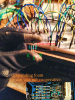
saw on the bottom of the sync, there was a need to apply grease there (pic), so did that as well. Glad I had enough left in the tube..

BottomSyncGrease.jpg

I brought it outside the house with a power strip, flipped it on, and it turned on with no issues.

I got excited and brought it in my office and rigged up the other powered monitors, got my breakout box and mac fired up to
play, turned it all on...

I heard the subwoofer and the other powered monitors fine :).

I then turned up the volume on the sub pre and I heard a little sound (poofish sound coming from the sub speaker not the inside).
That was it, no more sound coming from the sub woofer.. Still powered with clean expected sound coming from the mains) nothing exploded or caught on fire.

So, I think something is up with the pre-amp that drives the powered PCB or the board we worked on itself.
I clearly don't know the root cause yet.

I have to say, it was certainly a worthwhile process even though the result wasn't what I wanted.

I'm going to need to focus my attention on life's priorities (getting a new job) for now, but
I may pick this back up after the holidays depending..

Thanks much for all your help in this issue and educating me thru parts that were new territory for me!

You and Spec were indispensable in this journey.

Truly great humans, and awesome Electro-Tech Online forum!
 
Right then, The board could have damage parts else where, That diode that was cracked may be some point of interest. well then, good luck on the job search.
 
Yes, good point. I will take it out of the box to do an inspection, and take a few pics in case the
immediate damage is visible.. Snap shot in history if you will. Thanks for the good luck wishes.
I've got a few interviews lined up for this week. If all goes well there might be a few gifts under the tree
this year...

By the way, You're awesome, and thanks again!
 
Status
Not open for further replies.

Latest threads

New Articles From Microcontroller Tips

Back
Top