Continue to Site

Welcome to our site!

Electro Tech is an online community (with over 170,000 members) who enjoy talking about and building electronic circuits, projects and gadgets. To participate you need to register. Registration is free. Click here to register now.

  • Welcome to our site! Electro Tech is an online community (with over 170,000 members) who enjoy talking about and building electronic circuits, projects and gadgets. To participate you need to register. Registration is free. Click here to register now.

Remote Controlled Car

Status
Not open for further replies.

00TWINE

New Member
I think this is the best forum for this topic but if not I guess a mod can move it.

Anyways my friend and I are going to be building remote control cars and we need to know what we are doing. Our cars are going to be electric motors(possibly 4 wheel drive). We want to start out with just a remote control car and then customize them and add extra features like a tazer, saws, and other such things. All need to be able to be controlled by the same remote. Basically they are going to be battle bots sort of. More like a James Bond type car. If anybody has any suggestions or schematics or sites or anything that could be helpful to us, that would be greatly appreciated.
 
I'm doing somewhat the same thing but with a small radio-controlled robot. I'll use the DTMF tone generator (UM91210, UM91214, etc.) in combination with an FM transmitter for the remote and an FM receiver with DTMF decoder on the other end. This combination allows the usage of 16 functions and is very easy to implement.

Also, you could try the MC145026 encoder and MC145027 decoder from Motorola that does almost the same thing. It has 16 functions (via 4 bit data inputs) and can be interfaced via radio frequency or infra-red.


If you want, I can send you the schematics.
 
You guys can also use HT12E and HT12D from Holtek semiconductors. For schematic look at this site: www.rentron.com You'll have to seacrh the page but its there.
 
hello
i am also trying to build a remote control car ....but i dont know much about rf or fm transmission and receiving so can anyone provide some pcb schematic or such to build the remote control.....
 
I had an Idea that I've been toying with for a while. Since radio control sets with remotes and recievers are avilible pretty cheap on ebay, garage sales and such, but servo controlled throttle seems like an overly mechanical approach while premade solid state electrical throttles are fairly expensive, couldent you use a programmable microcontroller with PWM capture to read the signals that the reciver sent out for the servos, interpret it and convert it as needed, then use that information to controll a variable speed and direction PWM H-Bridge? Since I'm new to microcontrollers the first issue I imagine is that I dont think many chips can capture one pwm signal while producing another PWM signal on either of the two outputs to the h-bridge.
 
Last edited:
Triode, isn't that what a throttle control servo already does? NOt sure what you're trying to replace.
 
Sceadwian, well, both go from a pwm output from the receiver to a controlled power output, but this way does it with solid state components using just a chip and a h bridge instead of a servo which physically turns a variable resistor and hits a mechanical switch to reverse.

Thanks for the link Al
 
Oh you're talking about old resistive style throttles? I haven't seen those in years they're horribly ineffcient. You can buy solid state motor speed controls off the shelf from many makers, many reversible.
 
Last edited:
Oh you're talking about old resistive style throttles? I haven't seen those in years they're horribly ineffcient. You can buy solid state motor speed controls off the shelf from many makers, many reversible.

Yeah, they certainly have them but they're atleast $20 for one that controls one motor, this is a similar concept but to control more motors and in a more customizable way. I'm thinking of a tank drive vehicle, which would require two of those with linear proportionality in both directions. The ones you buy are usually designed for cars and have a sharp starting square root sort of curve, with a shorter one for reverse.
 
They START at 20 dollars =) But for good reason, the mosfets for higher power motor controllers are expensive, then again RC stuff always has a steep markup so making your own isn't a bad idea. Start a thread about it so we don't get acused of thread jacking =) (Starting a new topic in someone elses thread)
 
Its always a delicate balance between avoiding thread jacking and avoiding starting repetitive or useless threads. I figured this was fairly relevant to the topic.

But speaking of remote controlled vehicles, I know what a mosfet is, but how are they better for motor control? Also, I've been a little bit unclear about a few things in the motor control circuits I've looked at. How do you calculate what stats your transistors need to handle a given load? I would think since the motors are rated in Voltage and Amperage and the transistors are too that it would just match up, but it doesnt always seem to, on some of them the Wattage rating on the transistor is lower than the voltage x amperage of the motor, and from what I know that shouldent work out well. Is there some rule for it that I dont understand or are they just being inconsistent?

Likewise, what is the correlation between the rating of an inductive load you are controlling and the ratings required of the diode you use to protect the other circuitry from said inductive load?

I know its a lot of questions, but they are related to making RCs and while I've worked with electricity, the rules change a bit when you get down to the electronic scale, and I don't understand some of the differences.
 
For the current used in RC cars, Mosfets are almost always more efficient than transistors are. A mosfet does not drop voltage like a transistor does, it has an 'on state resistance' which can be VERY low, well bellow the equivalent voltage drop from a transistor.
Transistors tend to be more efficient at higher voltages than Mosfets, but RC is very low voltage.
 
I'm doing somewhat the same thing but with a small radio-controlled robot. I'll use the DTMF tone generator (UM91210, UM91214, etc.) in combination with an FM transmitter for the remote and an FM receiver with DTMF decoder on the other end. This combination allows the usage of 16 functions and is very easy to implement.

Also, you could try the MC145026 encoder and MC145027 decoder from Motorola that does almost the same thing. It has 16 functions (via 4 bit data inputs) and can be interfaced via radio frequency or infra-red.


If you want, I can send you the schematics.

can you please post the schematics please...:D
 
Rf remote controlled robot

hello,
can anyone help me...

i've recently finished my project titled "RF remote controlled robot".
actually the project is dc motor control using RF module and i've fitted wheels to the motors so it works as robot.
i'm attaching the abstract,circuit diagram

remote control transmitter part consists of 4 switches,based on which the controls are sent to the motor to rotate it in desired directions..
in my project i've pulled the TE(14 pin) of HT12E to gnd directly.....


now,my pblm is when i give the following commands at the switches the following is the result expected

0101-forward
1010-bckward
0001-left turn
0100-right turn
1001-left spin
0110-right spin
0010-left back
1000-right back

all these movements are working perfectly well....but only after some delay,

that is when i switch on the supply and press any switch the robot starts rotating in one particular direction and does not stop untill i manually stop it by switching off the power supply (even though i remove my finger by just touching the switch).....same is the case with any switch for abt 3-4 min...

after i manually stop the robot several times...(in abt 3-4 min) everything will be fine

soon after i touch a switch and leave the robot stops and the output is perfect for the above mentioned commands

i dont understand why there is this start up pblm?

can anyone pls help me?
 

Attachments

  • wireless motor control through RF.pdf
    223.5 KB · Views: 349
  • rf transmitter module.jpg
    rf transmitter module.jpg
    121.3 KB · Views: 374
  • robot with receiver module on board.jpg
    robot with receiver module on board.jpg
    136.8 KB · Views: 392
Without a schematic it is difficult to look for problem areas, but from the pictures it looks like you could use some decoupling capacitors. Try a large one, say 100ufd then some .1 ufd at each chip from +9 to ground.
 
@ronv

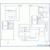
you can see the circuit diagram in this attachment....

do i need to correct anything in that?
 

Attachments

  • Wireless motor control through RF circuit_0.gif
    Wireless motor control through RF circuit_0.gif
    58.6 KB · Views: 1,135
Status
Not open for further replies.

Latest threads

New Articles From Microcontroller Tips

Back
Top