Continue to Site

Welcome to our site!

Electro Tech is an online community (with over 170,000 members) who enjoy talking about and building electronic circuits, projects and gadgets. To participate you need to register. Registration is free. Click here to register now.

  • Welcome to our site! Electro Tech is an online community (with over 170,000 members) who enjoy talking about and building electronic circuits, projects and gadgets. To participate you need to register. Registration is free. Click here to register now.

Remote control for winch

Status
Not open for further replies.

kinarfi

Well-Known Member
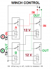
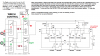
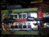
EDIT - FETs for high current, low voltage does appear to NOT work, I destroyed numerous PFETs and before they blew, the voltage drop across the H-Bridge FETs was around half of the 14.2VDC supply, so I didn't have enough power going to the winch to do what it was supposed to do. The last set of FETs that blew while I was trying to reel in the cable blew in such a way that the cable started reeling out and couldn't be stopped except for disconnecting the supply to them - Back to electro mechanically relays.

I have an off road vehicle and the stock winch control relay failed, so I made an H bridge using 2 PFETs in parallel and one NFET (IRF4905 & IRF1404Z) and I'm thinking of how to make a remote control for it. I was thinking of using one of those dual direction cord reels, but they are only about 8" long. How hard would it be to make an optical or RF remote with only 2 out puts that won't be bothered by bright direct sun light of interference from something like a CB radio. I haven't done anything with either yet, so any advise would be appreciated.
Thanks, Kinarfi
 
Last edited:
I cannot comment on the optical control as I have no real experience.

Radio would be a reasonable solution but be aware that there are safety implications with this. For example you dont want the winch to start turning when the cable is wrapped around your fingers!

With that in mind, if you used one of the small RF modules which are readily available, I think that the 315Mhz ones are the legally correct ones to use in the USA, be aware that there will be other users with similar modules and you could interfere with each other.
To prevent this, I would build the system so that the hand held controller sent a reasonably complex code which was unlikely to be replicated by an interfering signal.
At the winch end, I would ensure that the winch stopped if there was any doubt about the code.
I would also make sure that the motor controller could not latch on into a continuous run mode.

If you are using a 315Mhz module, I dont think that a 27Mhz CB would cause direct interference.
However, ensure that all control wiring is de-coupled for high frequencies as there is always the possibility of RF being picked up directly on the wiring and upsetting the controller.

JimB
 
How are you building an H-bridge with two PFET's and one NFET? :confused:
 
Paralleled PFETs, My understanding is that the PFET can't handle what the NFET can, so I paralleled them. Specs on the IRF4905 is -74 A and the specs on the IRF2805 is 175A(silicone) 75 A package limited. I used one resistor per side to turn on both NFETs and turn off both (all 4) PFETs and the ground signal to one side or the other turns on the PFET while turning off the NFET. Having both NFETs on creates dynamic braking from the motor and again, I use the NFETs because they're supposed to be more robust.
Kinarfi
 

Attachments

  • H-BRIDGE.asc
    2.5 KB · Views: 155
It really depends upon the current rating and ON resistance of the FETs.. If you buy a P-MOSFET with similar ratings to an N-MOSFET then you don't need to parallel the P-MOSFETs.
 
I am worried about the stall current of the winch, hopefully it will be less the capabilities of the FETs and I haven't found a PFET with a higher rating the -74 amps
 
Thanks Jim, looks like a good way to go
 
What kind of winch? I would think the stall current would be several hundred amps (my Warn pulls 400A under a moderate to heavy load). By off-road do you mean a truck/Jeep, or an ATV?

Why not just get a heavy-duty relay? Cheap and reliable. Even a Ford starter solenoid would work - not pretty looking but bulletproof for your application.

I think infrared should work fine. Just make it so you have to press the button continually to activate the winch, so a loss in signal stops the winch. Much safer than having separate ON/OFF buttons (what happens if you start the winch and the OFF button/signal doesn't work?).
 
adamey, the winch is on a Joyner Trooper T2 OHV, not as hefty or as good as your Warn, and stall current is my main worry, INHO, the current should burn the lead right off the NFET, but the data sheet says it can handle 75A, I plan to carry a bypass for emergency failures. I looked at infra red, but they don't have ready made modules like the RF remotes and the ones I'm looking at have a momentary setting which I will use, may eat batteries because it works only while pushing the button, something like this **broken link removed**, but I will take another look at mechanical relays.
Thanks
Kinarfi
another comment, my original set up that failed looks very similar to this one,**broken link removed** , one concern is that the coil draws 2 amps, that's 24 watts of heat and after a while the whole relay is too hot to touch.
 
Last edited:
Here is what I plan to use, after showing an earlier version to my son that blew up 3 PFETs. I would appreciate if others would examine my work and see if they can find any potential problems.
Thanks so much,
Kinarfi
 

Attachments

  • Winch Control.png
    Winch Control.png
    12.1 KB · Views: 201
  • Winch HBridge.png
    Winch HBridge.png
    23.4 KB · Views: 250
  • Winch Remote Control Unit.png
    Winch Remote Control Unit.png
    94.2 KB · Views: 194
  • Winch H-BRIDGE.asc
    4.8 KB · Views: 139
  • Winch Control 2.png
    Winch Control 2.png
    60.8 KB · Views: 341
Last edited:
Here's the "final" product prior to encasing and installation, works well, I have tested it several times by applying both in and out signals and had no failures.
 

Attachments

  • 20130621_103646.jpg
    20130621_103646.jpg
    3.4 MB · Views: 351
Edited the opening post, this experiment was a total bust!!!!
 
hi, why not just use new relay rated for the current and attach YOUR controllers to the relay inputs where the power is not so high?

not good idea though, if you plan to use PWm
 
hi, why not just use new relay rated for the current and attach YOUR controllers to the relay inputs where the power is not so high?

not good idea though, if you plan to use PWm

I did, no pwm, either full on or off, I'll be using 4 individual solenoids rated at 150 amp. the problem with stock unit was heat, so I don't think it was rated continuous and didn't have strong enough springs to make good contact, it was a chunk ov junk!!!!
 
Status
Not open for further replies.

Latest threads

New Articles From Microcontroller Tips

Back
Top