Continue to Site

Welcome to our site!

Electro Tech is an online community (with over 170,000 members) who enjoy talking about and building electronic circuits, projects and gadgets. To participate you need to register. Registration is free. Click here to register now.

  • Welcome to our site! Electro Tech is an online community (with over 170,000 members) who enjoy talking about and building electronic circuits, projects and gadgets. To participate you need to register. Registration is free. Click here to register now.

Relays for relay counter

Status
Not open for further replies.

Froskoy

New Member
Hi,

I want to have a go with using relays and as such I'm trying to follow this tutorial:
https://www.electro-tech-online.com/custompdfs/2009/11/relay-counter.pdf

So, I need to buy some relays! The place I order my electronics stuff from is rapid electronics and the only things they have that I can find that will do the trick (at a price I can afford) are:
**broken link removed**

Now I'm going to be building the thing on stripboard, but if I solder wires directly onto the contacts of the relay on the previous link, and then solder those wires onto the stripboard will that work?

I'm a bit apprehensive about working at 12V but it should be OK? I've got a power supply which will supply 12V 25A constant. When the relay says 10A, does that mean that its coil needs 10A? When I am testing, will feeding a 10A current into my oscilloscope be OK, even with the oscilloscope's very high resistance?

Just one final question: will the relays in the link I gave actually be suitable for the tutorial in the other link I gave?

Thanks very much,

Froskoy.
 
Last edited:
This could get expensive BUT!

3PDT relays are expensive but DPDT relays are more abundant and cheaper as are SPDT relays.
look at this link. they have several relays with quantity discounts.
as I see it you only need 2-SPST, 6-DPDT and 7 3PDT relays
if you get a large bread board you could just plug in the relays amd use LEDs instead of light bulbs.
Use 5,6,9,or 12volt coils. using LEDs will allow you to use smaller relays (cheaper and you can breadboard entire circuit and run it on batteries)
For the 3PDT relays the link has a 4PDT relay but cost.
If you buy 6 V coil DPDT relays then put a SPDT relay in series you now have a 3PDT relay running on 12v or 2 6v coil relays in parallel and run on a 6v power supply.
LOTS of options that are cheaper. Using LEDs is way cheaper as well.
then you could go with IC's

Relays-The Electronic Goldmine
 
Hi,

you might want to use relays with standard pitch of 1/10". The FINDER S30 fits exacly onto a DIL16 socket and is affordable as well.

That kind of relay is made by many manufacturers - so you don't have to purchase FINDER relays.

The advantage: A burnt up relay is easily exchanged when using a modified DIL16 socket (with excessive pins removed for easy trace routing)

Boncuk
 

Attachments

  • FINDER-S30.gif
    FINDER-S30.gif
    35.2 KB · Views: 712
Hmmm do you think that following a tutorial from a site with a retards.org domain is a good idea? :D Those projects seem to be mostly for laughs: Like the
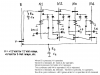
 desktop cell phone.
I'm a bit apprehensive about working at 12V but it should be OK? I've got a power supply which will supply 12V 25A constant.
There is no shock hazard when working with 12V. Watch the 25A current rating on the power supply though. Is the current limiting on the supply adjustable? If so, turn it down if your circuit uses a much lower current. ie: If your circuit will draw a max of 2A then set the limit on the supply to 3A. That will prevent smoke, sparks and fire if you accidentally short something out. If it isn't adjustable, a small inline fuse may be worth your while.
When the relay says 10A, does that mean that its coil needs 10A?
No. That would be the max contact rating. The coil current is usually a lot lower at around 10 to 100 mA.
When I am testing, will feeding a 10A current into my oscilloscope be OK, even with the oscilloscope's very high resistance?
Your scope will only directly measure voltage. If you want to measure current you need a shunt resistor and use ohms law to calculate the current from the voltage drop across the resistor.
 
Last edited:
Here is a relay counter & 2 relay FF circuits.

The FET used with the FF is required to do a "make before break" function.

Otherwise, the FF may not work since a SPDT contact goes open while in transit.
 

Attachments

  • Relay counter.png
    Relay counter.png
    83.3 KB · Views: 1,620
  • Relay latch.gif
    Relay latch.gif
    126.8 KB · Views: 619
  • Relay Flip Flop..gif
    Relay Flip Flop..gif
    7.8 KB · Views: 799
Yet a silent and cheap solution. For a four-pole double throw relay use one MAX312 (NC) and one MAX313 (NO). Connect all four control pins (1,8,9,16) instead of a relay coil.

The MAX312/313 can stand 100mA switching current at a voltage higher than +5V (separate +V pin)

Here are a schematic and a board design suggestion. Control pins must be connected for common operation of each pair of switches. Board size is 1.835X1.2inches.

Boncuk
 

Attachments

  • 4PDT-RELAY.gif
    4PDT-RELAY.gif
    11.6 KB · Views: 734
  • 4PDT-RELAY-BRD.jpg
    4PDT-RELAY-BRD.jpg
    38.8 KB · Views: 499
Last edited:
The FET used with the FF is required to do a "make before break" function.

Otherwise, the FF may not work since a SPDT contact goes open while in transit.

Looks like "break before make" to me.
 
Whereas, a SPDT contact is break before make.

That's exactly what you would expect a relay to do.

"Make before break" could sometimes have fatal consequences. :)

The result is important. What happens before throwing relay conctacts is no point of interest. (except for unintended shorts). :)

I sometimes have the impression Australians have invented electronics, but allas, you're 543 years late. Thais have invented the sun, the moon, electric energy and even computers. :D

Due to their generousity they left their inventions to the rest of the world never thinking about the profit they could make out those epoche breaking engineering capabilities. :D :D

BTW, it was a German named Konrad Zuse who invented the first relay driven computer taking up 40 square meters of space.

I'm German, too. :p

Got me?

Regards

Boncuk (also called Herman the German, Russians used to call me "Zoni, the destroyer without weapons")
 
That's exactly what you would expect a relay to do.

"Make before break" could sometimes have fatal consequences. :) See below

The result is important. What happens before throwing relay conctacts is no point of interest. (except for unintended shorts). :) See below

I sometimes have the impression Australians have invented electronics, but allas, you're 543 years late. Thais have invented the sun, the moon, electric energy and even computers. :D

Electronics were invented by people in many countries.

Due to their generousity they left their inventions to the rest of the world never thinking about the profit they could make out those epoche breaking engineering capabilities. :D :D

BTW, it was a German named Konrad Zuse who invented the first relay driven computer taking up 40 square meters of space.

I'm German, too. :p

Got me?

Regards

Boncuk (also called Herman the German, Russians used to call me "Zoni, the destroyer without weapons")
Many years ago, I worked on the design of complex relay systems for electromechanical telephone exchanges.

There were "make before break" contacts available that were used to prevent race conditions.

There were also "X" and "Y" contacts which were designed to make first (X contacts) and make last (Y contacts). These were also necessary for timing reasons.

The counter I posted above is a simplification of a counter that was used in telephone exchanges to count pulses from the telephone dial.

The attachment is a copy of that counter, copied from a training manual. It counts 1 ~ 10 pulses. For example, after 3 pulses, N3 will be the only relay operated. But after say 8 pulses, N3 & N6 will be operated.

Note that relays N1 ~ N5 have 2 coils. One was the operate coil, the other the hold coil. In my version, I used diodes instead as I don't think you can buy dual coil relays now.

The NA relay repeats the dial pulses to the counter.
 

Attachments

  • Dial Pulse Counter.gif
    Dial Pulse Counter.gif
    29.4 KB · Views: 562
Last edited:
On some relays it's possible to convert a break-before-make contact set into make-before-break by carefully bending the outer contacts towards the common contact. They have to be bent far enough that when the common contact is in mid-travel position, all three are touching. When the common contact reaches its full travel, it draws the one contact with it breaking the other contact.
 
Many years ago, I worked on the design of complex relay systems for electromechanical telephone exchanges.

There were "make before break" contacts available that were used to prevent race conditions.

There were also "X" and "Y" contacts which were designed to make first (X contacts) and make last (Y contacts). These were also necessary for timing reasons.


Note that relays N1 ~ N5 have 2 coils. One was the operate coil, the other the hold coil. In my version, I used diodes instead as I don't think you can buy dual coil relays now.

The NA relay repeats the dial pulses to the counter.

Hi Len,

I've seen those (similar) relays in the early 50s at a telephone switching room (hall) of Deutsche Telekom. They stepped 10 up ten and rotated 10 - puh, what a devastating noise of more than 20,000 relays clicking in one room. (Moving up the sound was "rat - rat" and rotating it was "click - click")

At the end of my visit I got a "used up" sample for free, cleaned the contacts and used it for a switchable bench power supply to switch transformer taps accordingly. To make it easy I also used a telephone dialing unit - zeroing before a new setting was accomplished.

And yes, dual coil relays are still available on the market. They are commonly called "bistable" or "latching" relays.

FINDER applies another solution with a single coil which must be reversed to change switch condition.

Boncuk
 
As another old telephone man from the days of cross-bar switches, I’m surprised that anybody is still interested in this old technology. I think I still remember how a Marker and an Incoming Sender went together, but I would be really hard pressed to have to fix a Decoder or Card Translator. The flat spring U-type was obsolete by ’69 and nearly everything was wire spring. I found flat spring relays in European built PBX systems well into the late ‘70s.
 
Hi Len,

I've seen those (similar) relays in the early 50s at a telephone switching room (hall) of Deutsche Telekom. They stepped 10 up ten and rotated 10 - puh, what a devastating noise of more than 20,000 relays clicking in one room. (Moving up the sound was "rat - rat" and rotating it was "click - click")
This sounds like a bimotional switch. ie. a step by step exchange. Yes they were noisy. I worked on Ericsson crossbar, ARF, ARK & ARE. The counter is from an ARF register.
At the end of my visit I got a "used up" sample for free, cleaned the contacts and used it for a switchable bench power supply to switch transformer taps accordingly. To make it easy I also used a telephone dialing unit - zeroing before a new setting was accomplished.

And yes, dual coil relays are still available on the market. They are commonly called "bistable" or "latching" relays. The relays made by Ericsson shown in the counter drawing are not bistable. You could not use bistables in that circuit.

FINDER applies another solution with a single coil which must be reversed to change switch condition.

Boncuk
I don't understand you last sentence. I think you must be referring to the relay counter posted earlier in this thread. It needed 8 relays for a Mod 4 counter.

The circuit I posted, based on the Ericsson counter but using diodes in lieu of dual coils, only needs 4 relays.

In fact it could be done with 2 relays (2 relay => 4 states) but it would be difficult to make it reliable due to the difficulty of handling the state transitions.

I once saw a Mod 10 counter in a Siemans trunk exchange that only used 4 relays. But it was dreadful since they needed both X and XX contacts to prevent timing races. It required a lot of maintenance.

The Ericsson solution is much more elegant & reliable because they avoid the timing races by using 6 relays.
 
Last edited:
As another old telephone man from the days of cross-bar switches, I’m surprised that anybody is still interested in this old technology. I think I still remember how a Marker and an Incoming Sender went together, but I would be really hard pressed to have to fix a Decoder or Card Translator. The flat spring U-type was obsolete by ’69 and nearly everything was wire spring. I found flat spring relays in European built PBX systems well into the late ‘70s.
Was it the Ericsson ARF system?
 
I don't understand you last sentence.

The last sentence referred to the FINDER 41.61 series bistable relay. To reverse relay function the coil voltage must be reversed as well.
 
Thanks Boncuk.
Yes I realised what you meant later when reviewing the posts.

I guess it would be possible to design a counter using latching relays, but it may be tricky to do the state transitions given that you need to apply a reverse voltage reset pulse to release the relay - as you wrote.
 
Status
Not open for further replies.

Latest threads

New Articles From Microcontroller Tips

Back
Top